
Decoy technology

Inactive Publication Date: 2007-06-21
CRAIN DOUGLAS L
View PDF45 Cites 0 Cited by
  • Summary
  • Abstract
  • Description
  • Claims
  • Application Information

AI Technical Summary

Benefits of technology

[0009] The invention provides a decoy apparatus and method which are practical, reliable, accurate and efficie

Problems solved by technology

This technology is believed to have significant limitations and shortcomings.

Method used


Image

  • Decoy technology
  • Decoy technology
  • Decoy technology

Examples


Embodiment Construction

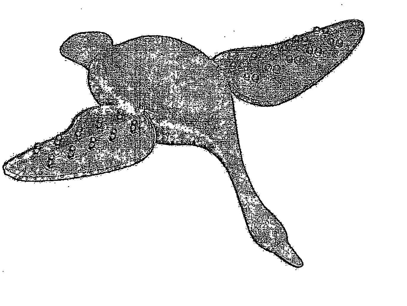
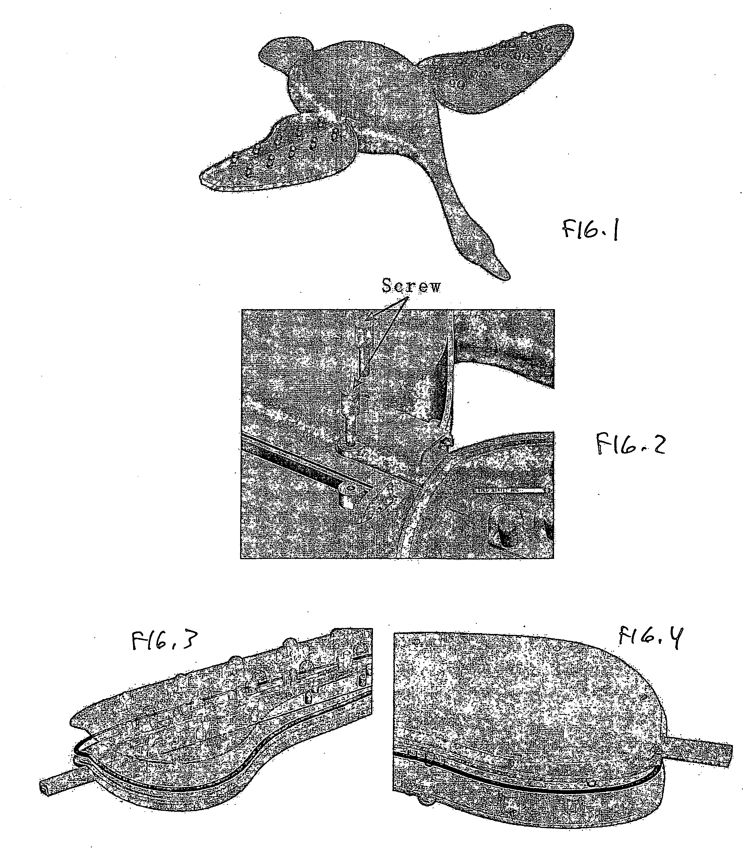
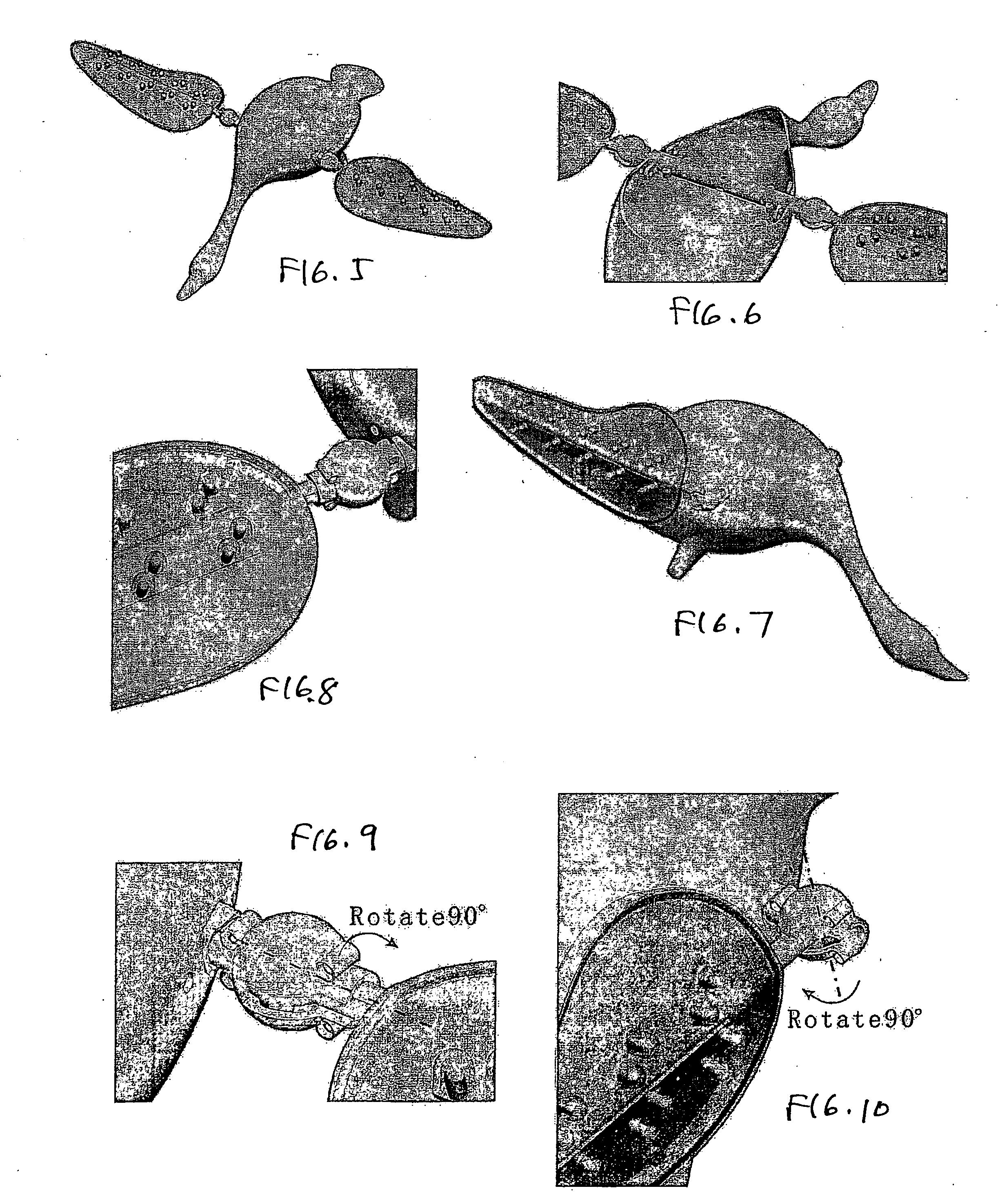
[0013]FIGS. 1-19 illustrate embodiments or the decoy of the present invention, assemblies or parts thereof, and methods thereof.

[0014] The apparatus of the invention is a decoy including a body, a stake extending from the body for connection to earth, and wings extending from the body. The wings have a first surface which has a convex or convex-like configuration. The surface may be rectilinear, curvilinear or a combination thereof. Lights, preferably LEDs, are constructed and arranged relative to the first surface such that they emit light away from the first surface and to the environment. The LEDs are selectively activated so as to simulate wing movement. A power source, such as a battery, and a control circuit are communicatively connected to the LEDs for activation.

[0015] Embodiments of the decoy apparatus of this invention are useful to hunters and birders. The apparatus may be controlled or regulated by individual state Natural Resource Departments.

[0016] Existing spinning...


PUM


Abstract

A decoy including a body, a stake extending from the body for connection to earth, and wings extending from the body. The wings have a first surface which has a convex or convex-like configuration. Lights, preferably LEDs are constructed and arranged relative to the first surface such that they emit light away from the first surface and to the environment. The LEDs are selectively activated so as to simulate wing movement.

Description

BACKGROUND OF THE INVENTION [0001] 1. Field of the Invention [0002] The present invention relates, generally, to sporting and recreational equipment. Particularly, the invention relates to hunting and birding decoy equipment. Most particularly, the invention relates to a lighted wing bird decoy. [0003] 2. Background Information [0004] The state of the art includes various bird decoys, including a decoy design described in U.S. Pat. No. 6,460,284, issued Oct. 8, 2002 to Rabo. This patent discloses a decoy with a buoyant body, a wing simulating structure with an upwardly dished upper surface, and LEDs positioned to illuminate the upper surface of a wing simulating structure. [0005] Other patents of potential interest include U.S. Pat. Nos. 6,408,559, 6,508,028, and D469152 [0006] This technology is believed to have significant limitations and shortcomings. [0007] For this and other reasons, a need exists for the present invention. [0008] All US patents and patent applications, and all...

Claims


Application Information

Patent Timeline
IPC IPC(8): A01M31/06
CPCA01M31/06
Inventor CRAIN, DOUGLAS L.
Owner CRAIN DOUGLAS L
Learn More