Charge conditioner technology

a charge conditioner and charge technology, applied in the direction of particle separator tube details, instruments, nuclear engineering, etc., can solve the problems of difficult transport and maintenance of radioactive and corona sources, interference with measurement, and unsatisfactory radioactive sources, so as to facilitate the quantification of aerosol concentration, and the effect of reliable and reliabl

Active Publication Date: 2018-10-25
KANOMAX FMT INC
View PDF0 Cites 0 Cited by
  • Summary
  • Abstract
  • Description
  • Claims
  • Application Information

AI Technical Summary

Benefits of technology

[0014]The invention provides a soft X-ray charge conditioner system, apparatus, and method which are practical, reliable, accurate and efficient, and which are believed to fulfill the need and to constitute an improvement over the background technology.
[0015]Aerosol charge conditioning applies a known charge distribution to aerosol particles which facilitates quantification of aerosol concentration following electrical measurement methods (electrostatic classification, electrometer measurement).

Problems solved by technology

Radioactive sources are not ideal due to regulatory requirements as well as a decay in the total radiative power over time.
In summary, radioactive and corona sources are difficult to respectively transport and maintain.
However, direct exposure of some gases to soft x-ray radiation can create electrolytically generated aerosol particles which may interfere with the measurement.
While this method is effective for general charge conditioning, it does not allow for controlled charging ion creation (chemical ionization).
Existing technology in this field is believed to have significant limitations and shortcomings.

Method used


Image

  • Charge conditioner technology
  • Charge conditioner technology
  • Charge conditioner technology

Examples


Embodiment Construction

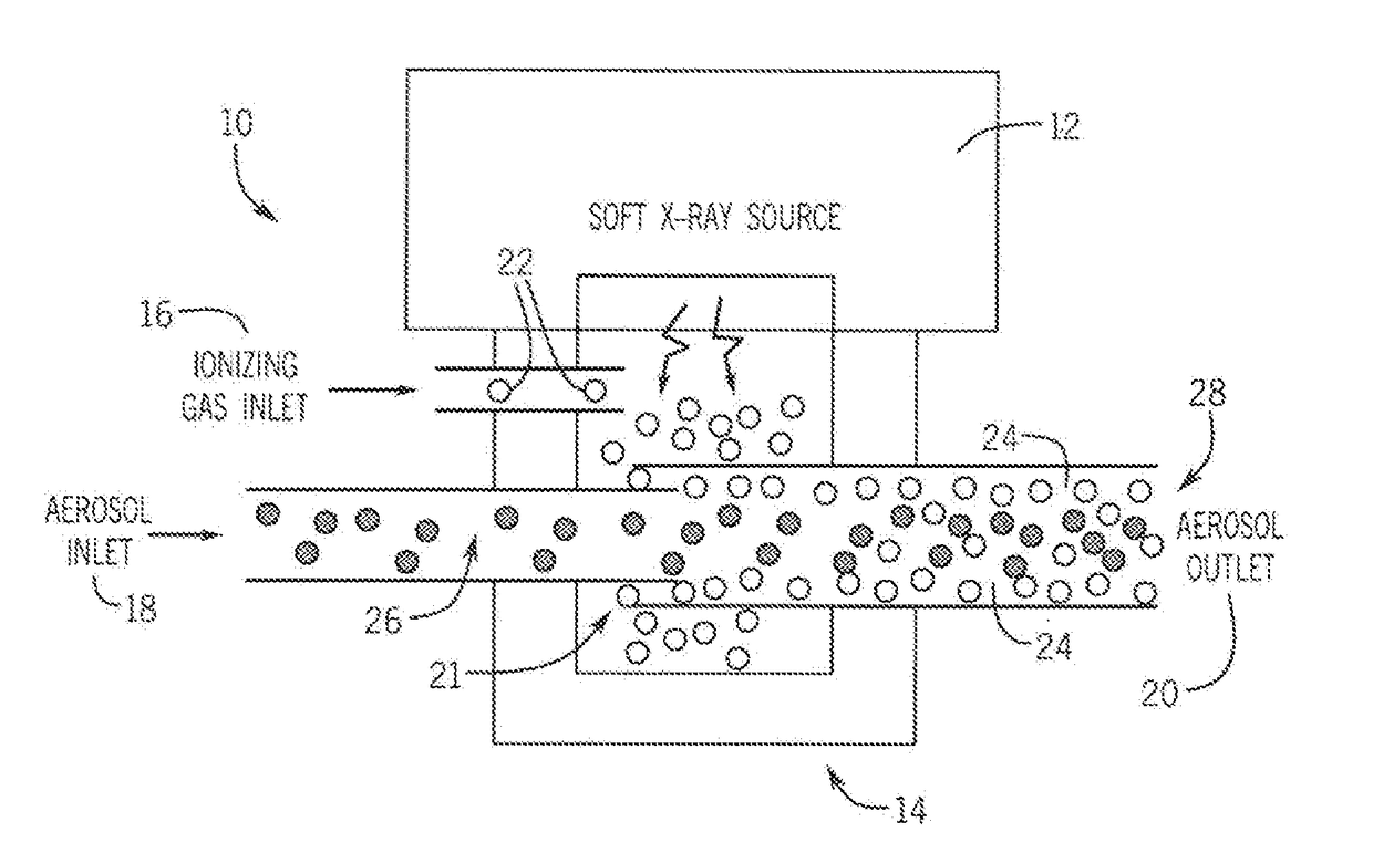
[0037]FIG. 1 is a diagram of an embodiment of the system, apparatus and method of the present invention. This embodiment of the invention utilizes indirect radiation, particularly soft X-ray radiation. The system does not expose aerosol to ionization energy. It permits prescribed chemical ionization. A sheathed configuration reduces diffusional losses.

[0038]The charge conditioner 10 basically comprises a radiation source 12, an ionization housing 14, an ionizing gas inlet 16, an aerosol inlet 18, and an aerosol outlet 20. Ionizing gas of a controlled composition is introduced, via inlet 16, into the ionization housing 14 where it is exposed to soft x-ray radiation generated by the source 12. The ionized gas molecules 22 are then introduced, via inlet 18, as a sheath flow 24 around an aerosol stream 26 (formed of a sample input at the proximal end of inlet 18) where the aerosol particles 26 are then charged from collisions with ions 22 diffusing through the aerosol stream 26. The she...


PUM


Abstract

An aerosol charge conditioner includes a source of ionizing radiation, an ionization region, and a conduit transporting an aerosol sample through the ionization region. The conduit is constructed and arranged to control irradiation of the aerosol sample. The conduit includes an inlet conduit communicatively connected to an outlet conduit. The inlet conduit has a first diameter and a distal end disposed in the ionization region. The outlet conduit has a second diameter which is greater than the first diameter of the inlet conduit and a proximal end disposed in the ionization region. A secondary gas supply is communicatively connected to the ionization region. A method for controlled ionization of aerosol particles using radiation as a source is also disclosed.

Description

CROSS-REFERENCE TO RELATED APPLICATIONS, IF ANY[0001]This application claims the benefit under 35 U.S.C. § 119(e) of co-pending U.S. Provisional Patent Application Ser. No. 62 / 488,361, filed Apr. 21, 2017, which is hereby incorporated by reference.37 C.F.R. § 1.71(E) AUTHORIZATION[0002]A portion of the disclosure of this patent document contains material which is subject to copyright protection. The copyright owner has no objection to the facsimile reproduction by anyone of the patent document or the patent disclosure, as it appears in the US Patent and Trademark Office patent file or records, but otherwise reserves all copyright rights whatsoever.STATEMENT REGARDING FEDERALLY SPONSORED RESEARCH OR DEVELOPMENT[0003]Not applicable.REFERENCE TO A MICROFICHE APPENDIX, IF ANY[0004]Not applicable.BACKGROUND OF THE INVENTION1. Field of the Invention[0005]The present invention relates, generally, to aerosol particle charge conditioning. Particularly, the invention relates to aerosol partic...

Claims


Application Information

Patent Timeline
Patent Type & Authority Applications(United States)
IPC IPC(8): H01J49/04H01J49/14
CPCH01J49/0445H01J49/145G01N2015/0046G01N15/0656G21K5/10H05F3/06B01J19/125
Inventor OBERREIT, DEREK
Owner KANOMAX FMT INC
Why Eureka
Try Eureka