Column design for micro gas chromatograph

a gas chromatograph and microcolumn technology, applied in the direction of dispersed particle separation, instruments, separation processes, etc., can solve the problems of insufficient individual carrying capacity, inconvenient use, and insufficient size of conventional gcs, etc., to achieve good gc resolution

Active Publication Date: 2012-02-28
THE BOARD OF TRUSTEES OF THE UNIV OF ILLINOIS
View PDF225 Cites 25 Cited by
  • Summary
  • Abstract
  • Description
  • Claims
  • Application Information

AI Technical Summary

Benefits of technology

[0009]The invention provides improved column channel structures and methods for producing channel structures suitable for use in μGC. In particular, the columns may be constructed using a particular channel structure, such as a serpentine channel structure, having various bend geometries for μGC separation, resulting in good μGC resolution.

Problems solved by technology

Conventional GCs are very bulky and are not small enough to be carried by individuals.
Previous work on μGC, however, has concentrated on columns that are arranged with a spiral geometry as shown in FIG. 1, Panel A. Research done by applicants indicates that the spiral channel configuration may not be well suited for microanalytical system, as discussed below.

Method used


Image

  • Column design for micro gas chromatograph
  • Column design for micro gas chromatograph
  • Column design for micro gas chromatograph

Examples


specific example 1

Design and Fabrication of Micro-Columns

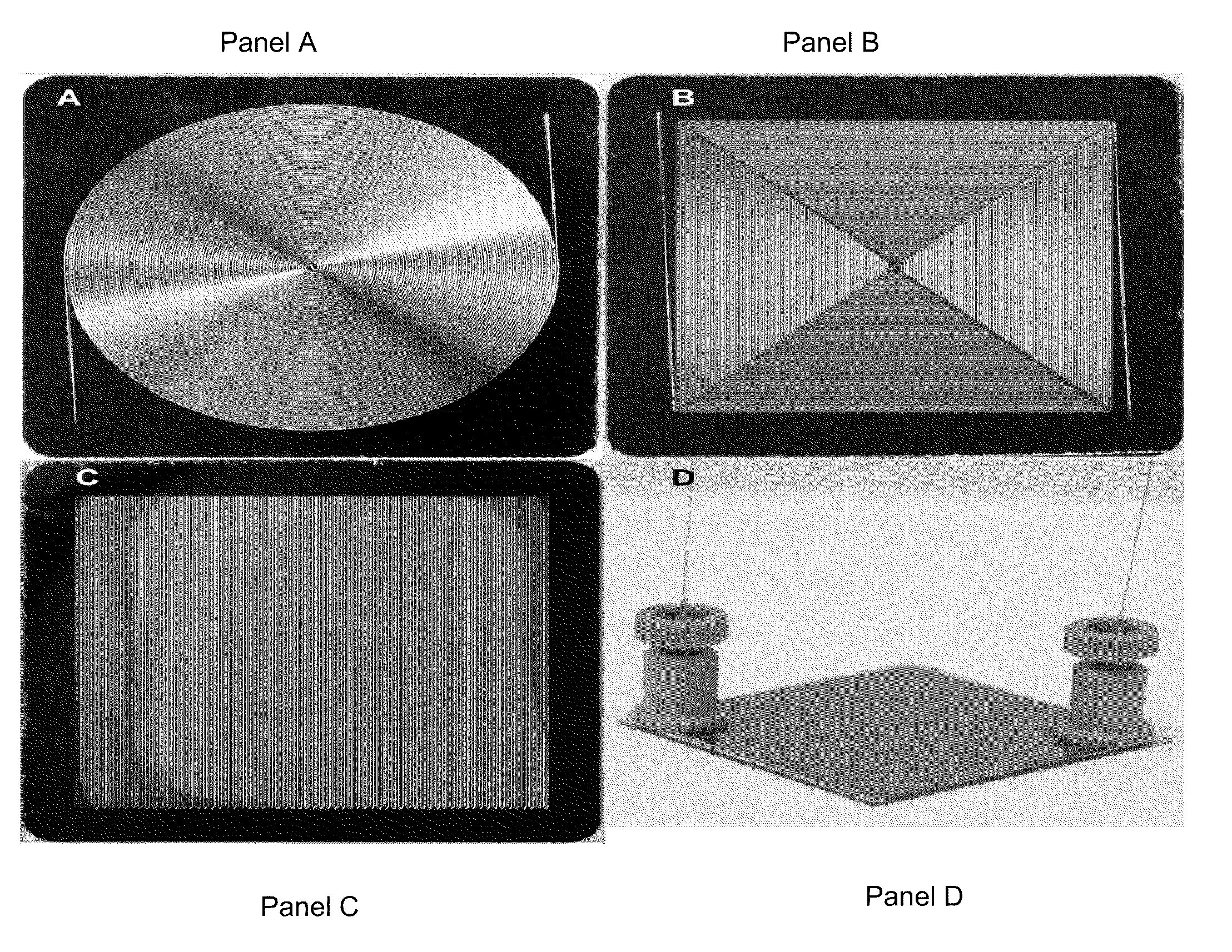
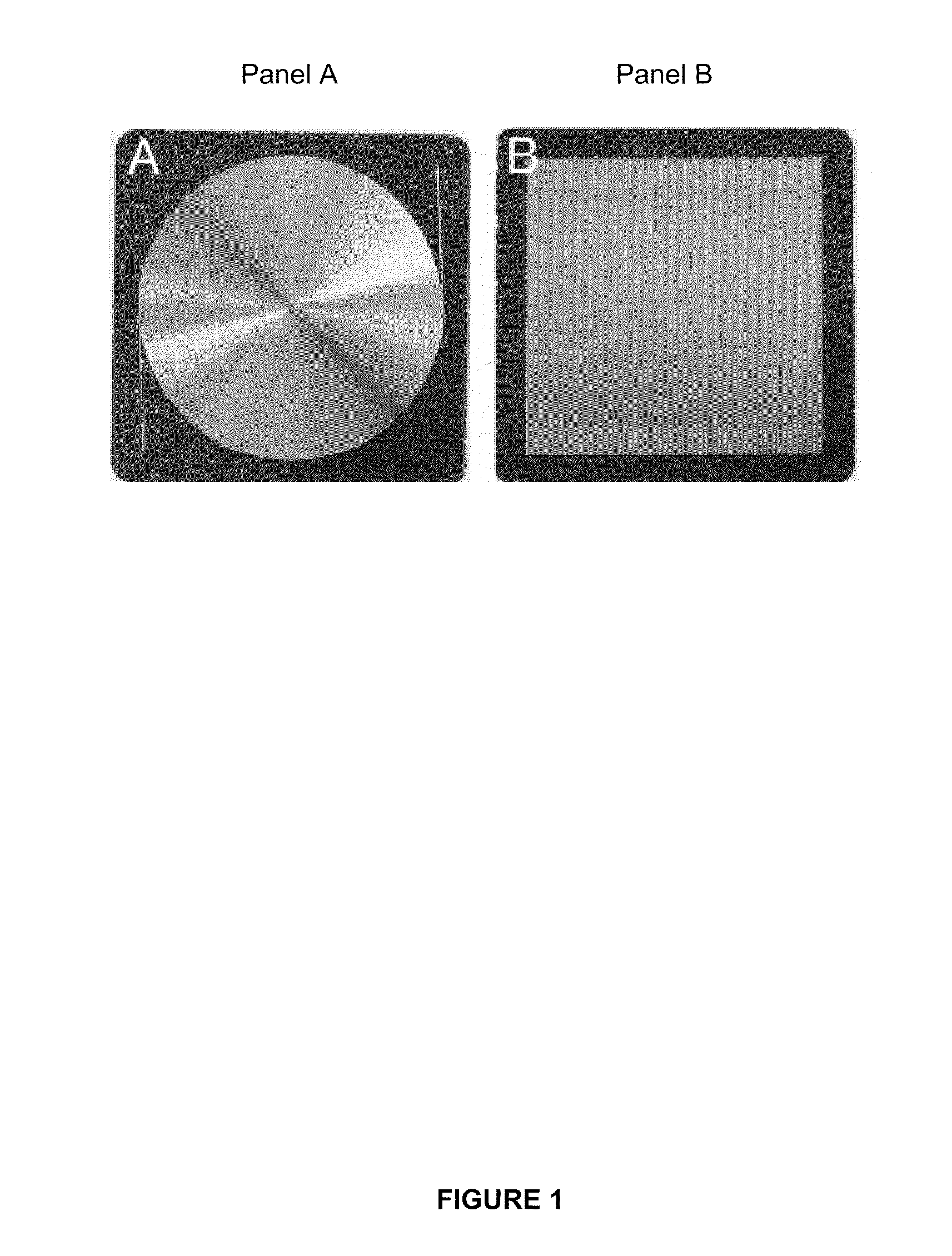
[0093]Microfabrication started with a double side polished silicon wafer (4″ diameter, 250 μm thick, 5-20 ohms-cm p-type) from Silicon Quest International. The wafer was sputter coated with 1000 Å thick aluminum on one side. The aluminum layer protected the silicon surface from getting damaged during the fabrication steps prior to anodic bonding. Shipley SPR220-7 photoresist was spin-coated on both sides of the wafer at 3000 rpm. Double side lithography was performed to obtain an image of micro-channels on the aluminum side and fluid transfer holes on the silicon side. The chrome mask set for lithography was fabricated by Photo Sciences Inc. using a laser pattern generator. Micro-channel mask consisted of four 3.2 cm×3.2 cm dies each filled with 100 μm wide and 3 m long micro-channel folded in serpentine, circular-spiral, or square-spiral configuration. The serpentine micro-column design consisted of 25.9 mm long straight segments and turns of ...

specific example 2

Passivation of Micro-Columns

[0094]Organosilicon hydride passivation using phenyltris(dimethylsiloxy)silane (Ah3P) (Gelest, SIP6826) was performed as disclosed in U.S. Appln. No. 61 / 021,620. The passivation was performed by dynamically coating the surface with a one micro-column length plug of neat reagent. A brass reservoir manifold containing the solution was attached on one of the micro-column access ports and the plug was pulled using a 660.4 mm Hg vacuum at the second access port. After the liquid plug exited the micro-column was heat-treated in a vacuum annealer (300 microns Hg) at a rate of 8° C. min−1 to 375° C. and holding at the final temperature for 4 hours. The vacuum annealer was purged with nitrogen for 20 minutes before applying vacuum to ensure oxygen absence. The micro-column was cooled to room temperature before exposing to atmosphere.

specific example 3

Stationary Phase Coating

[0095]5% polar stationary phase, OV-5 vinyl gum obtained from Ohio Valley Specialty Company (Marietta, Ohio) was used as the stationary phase. The coating solutions were prepared in hexamethyldisilazane treated 12×32 vials obtained from Alltech (#72670). The stationary phase (in the range of 0.05-0.07 gm) was transferred to a vial using the closed end of a melting point capillary (Fisher Scientific, 12-141-5). 0.2 μm filtered pentane was injected into the capped vial using a 500 ml gas-tight syringe (Supelco, 509485) to produce a 4% (w / v) coating solution. The phase was dissolved by sonicating the vial for 20 minutes. Dicumyl peroxide (DCP) (Sigma Aldrich, >99%) in the form of freshly prepared 2% (w / v) toluene solution was added to the coating solution using a 10 μL syringe (Agilent Technologies, 5181-3354) to achieve a concentration of 0.2% (w / w) of the stationary phase.

[0096]The coating procedure was slightly modified from the methodology disclosed in U.S. ...


PUM


Abstract

Improved micro-columns and methods for producing micro-columns particularly suitable for use in gas chromatographs are disclosed. In particular, following deposition of the stationary phase coating, the micro-columns are subjected to a postcoating treatment with a molecule that binds to the active sites in the stationary phase micro-column thereby eliminating or reducing loss of gas chromatograph performance associated with those active sites. The postcoating treatment molecule binds to the same active sites as the analytes of interest.

Description

CROSS-REFERENCES TO RELATED APPLICATIONS[0001]This application claims priority to and benefit under 35 U.S.C. §119(e) to U.S. Provisional Application Ser. Nos. 61 / 021,588 and 61 / 021,620, both filed Jan. 16, 2008, the disclosures of which are herein incorporated by reference in their entirety.STATEMENT AS TO RIGHTS TO INVENTIONS MADE UNDER FEDERALLY SPONSORED RESEARCH OR DEVELOPMENT[0002]This invention was made, at least in part, with U.S. government support under the Defense Advanced Research Projects Agency (DARPA) under U.S. Air Force Grant F A8650-04-1-7121. The Government has certain rights in this invention.BACKGROUND OF THE INVENTION[0003]1. Field of the Invention[0004]The invention relates generally to novel micro-column designs for micro-gas chromatography (μGC) micro-columns, such as serpentine micro-columns, which give relatively lower height equivalent to theoretical plate (HETP) values. Turns are a major dispersion source for serpentine configuration and sinusoidal compe...

Claims


Application Information

Patent Timeline
Patent Type & Authority Patents(United States)
IPC IPC(8): B01D53/02
CPCG01N30/6095G01N2030/0095G01N2030/025
Inventor MASEL, RICHARD ISHANNON, MARKRADADIA, ADARSH D
Owner THE BOARD OF TRUSTEES OF THE UNIV OF ILLINOIS
Why Eureka
Try Eureka