Intake air introducing structure for automobile

a technology for introducing structures and intake air, which is applied in the direction of combustion air/fuel air treatment, machines/engines, transportation and packaging, etc., can solve the problems of not being configured to meet such criteria, and achieve the effect of increasing the support strength of the intake air introduction port and good appearan

Active Publication Date: 2012-03-06
HONDA MOTOR CO LTD
View PDF28 Cites 31 Cited by
  • Summary
  • Abstract
  • Description
  • Claims
  • Application Information

AI Technical Summary

Benefits of technology

[0012]Accordingly, introduction of the outside air into the intake air introduction port is not prevented even if the grill cover is provided and blocks the front grill and the bulkhead. Also, the grill cover covers a space between the front grill and the bulkhead so that the front grill and the bulkhead are not exposed to the outside, therefore, the grill cover provides a good appearance, and can further prevent tools, such as for maintenance of devices around the engine, from falling into the intake air guide member.
[0013]According to a fifth feature of the present invention, the intake air introduction port is disposed in a position that is higher than the bulkhead and is secured to a stay mounted to the bulkhead. As such, the outside air is easily guided to the intake air introduction port without being interrupted by the bulkhead, and the support strength of the intake air introduction port is increased.

Problems solved by technology

However, the structure disclosed in JP '252 is not configured to satisfy such a criteria.

Method used


Image

  • Intake air introducing structure for automobile
  • Intake air introducing structure for automobile
  • Intake air introducing structure for automobile

Examples


Embodiment Construction

[0024]An embodiment of the present invention will be described below with reference to the attached drawings.

[0025]In the following description, the terms “front, rear”, “left, right” and “upper, lower” are used with reference to a front side in an advancing direction of an automobile.

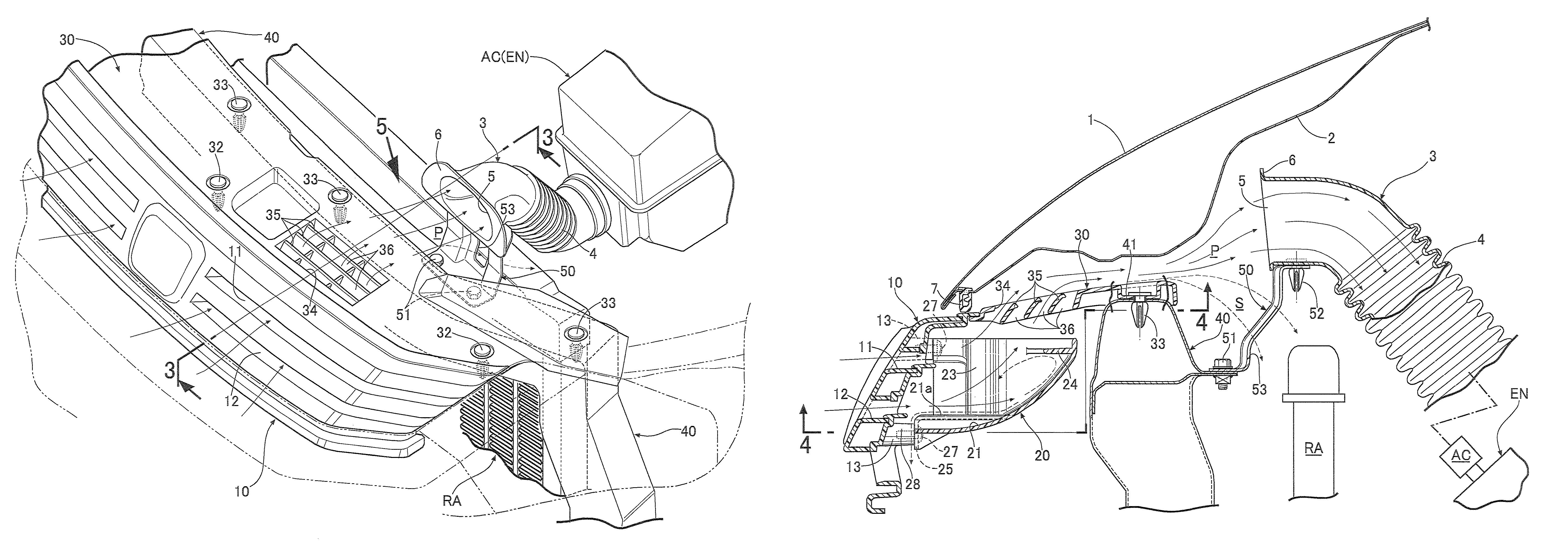
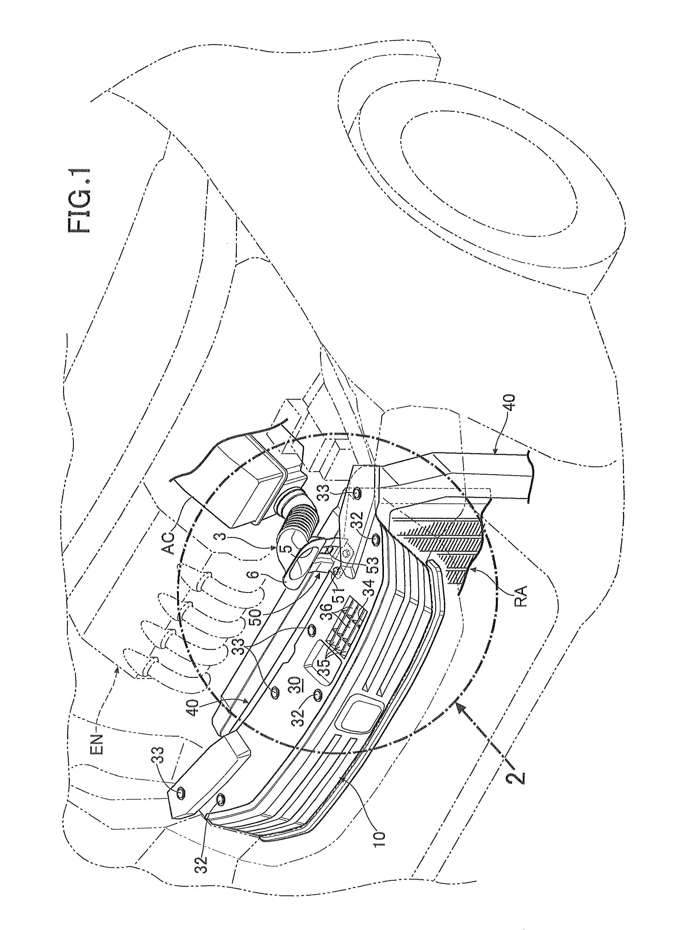
[0026]In FIGS. 1 to 3, an engine room located in front of a driver seat and covered by a hood panel 1 of an automobile houses an engine body EN and a radiator RA. A bulkhead 40 is provided between the radiator RA and a front grill 10 in a front end of an automobile body.

[0027]An intake duct 3 is connected to an inlet of an air cleaner AC connected to an intake system of the engine body EN. The intake duct 3 has a bellows tube 4 in an intermediate portion thereof, is formed into a gooseneck shape and extends forward above the radiator RA. A front portion of the intake duct 3 is supported by a stay 50, which will be described later, that is secured to the bulkhead 40. An intake air introduction port 5 is...


PUM


Abstract

An intake air introducing structure for an automobile includes an intake air guide member provided between a front grill and a radiator. The intake air guide member is open at front and upper sides, and has a curved guide surface that inclines upward from a bottom side toward a rear side and has a curved shape that protrudes downward. A block wall protrudes toward a side of the curved guide surface and is provided in an upper portion of the curved guide surface.

Description

CROSS-REFERENCE TO RELATED APPLICATION[0001]This application claims the priority of Japanese Application No. 2009-1809, filed Jan. 7, 2009, the entire specification, claims and drawings of which are incorporated herewith by reference.BACKGROUND OF THE INVENTION[0002]1. Field of the Invention[0003]The present invention relates to an intake air introducing structure which introduces outside air from a front grill located at a front portion of an automobile body into an intake system of an engine in an automobile.[0004]2. Description of the Related Art[0005]A conventional intake air introducing structure for an automobile is disclosed in Japanese Patent Application Laid-Open No. 2002-211252 (JP '252) wherein outside air introduced through a front grill into an automobile body is guided through a radiator core support outer panel provided in a gap between a hood panel and a radiator to a nozzle introduction port of an intake duct provided in a rear upper position of the radiator.[0006]I...

Claims


Application Information

Patent Timeline
Patent Type & Authority Patents(United States)
IPC IPC(8): B60K13/02B60K11/08
CPCB60K11/08B60K13/02F02M35/04F02M35/10013F02M35/10144F02M35/10262F02M35/161F02M35/10137Y02T10/146Y02T10/12
Inventor TERAGUCHI, SUNAOOKAGAWA, YOHEI
Owner HONDA MOTOR CO LTD
Why Eureka
Try Eureka