Computer graphics rendering apparatus and method

a computer graphics and apparatus technology, applied in the field of computer graphics rendering apparatus and computer graphics rendering method, can solve the problems of half the total capacity of the cache, the conflict of cache lines may occur among, and the increase in the cost of the circuit due to the increase in associativity

Inactive Publication Date: 2012-03-06
KK TOSHIBA
View PDF4 Cites 1 Cited by
  • Summary
  • Abstract
  • Description
  • Claims
  • Application Information

AI Technical Summary

Problems solved by technology

Therefore, a conflict of a cache line may occur among these images.
However, in the associative approach, an increase in a circuit cost due to an increase in associativity poses a problem.
Further, in the division approach, it is likely that only a half of the total capacity of the cache is used in some case.
Therefore, in the division approach, deterioration in efficiency of the cache poses a problem.
As described above, in the associative approach and division approach, wastes related to caching of texture images, such as an increase in a circuit cost and deterioration in efficiency of the cache, pose problems.

Method used


Image

  • Computer graphics rendering apparatus and method
  • Computer graphics rendering apparatus and method
  • Computer graphics rendering apparatus and method

Examples


Embodiment Construction

[0020]Embodiments of the present invention will be described with reference to the drawings.

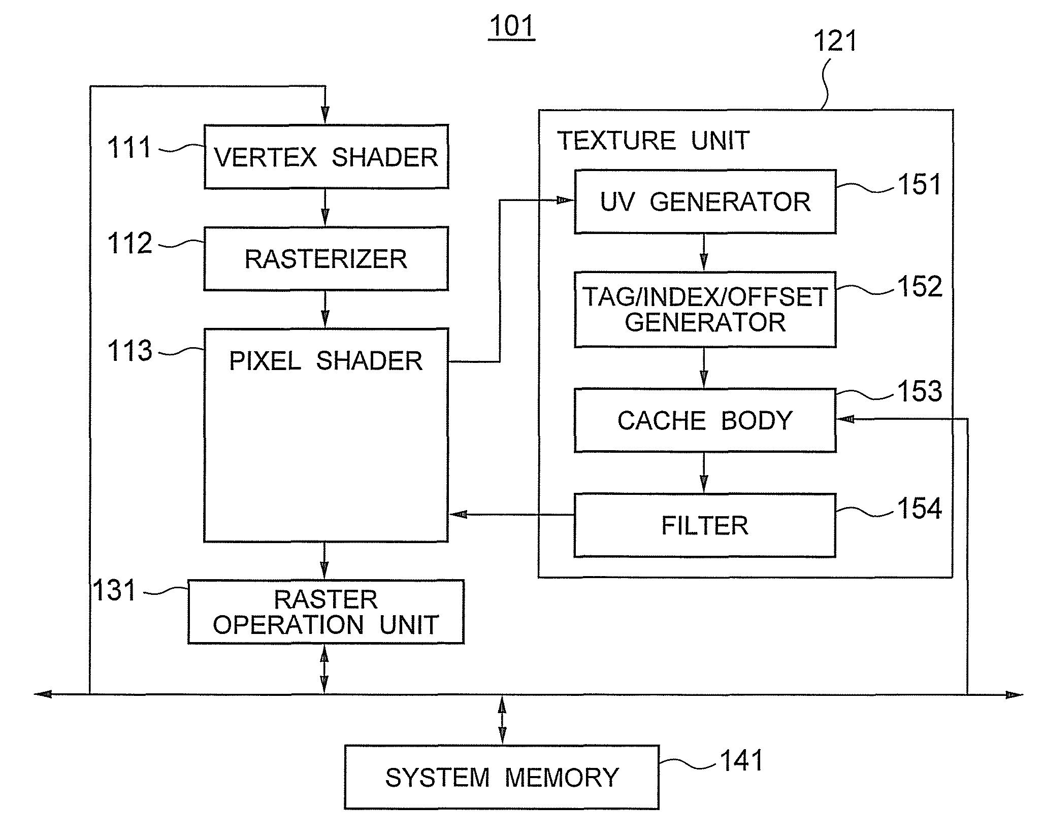
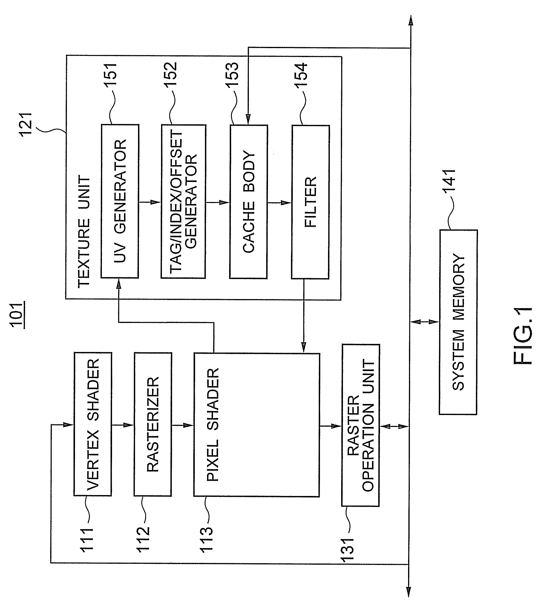
[0021]FIG. 1 is a block diagram of a computer graphics rendering apparatus 101 according to an embodiment of the present invention. The rendering apparatus 101 in FIG. 1 includes a vertex shader 111, a rasterizer 112, a pixel shader 113 as an example of a first coordinate generating unit, a texture unit 121, a raster operation unit 131, and a system memory 141. The texture unit 121 includes a UV generator 151 as an example of a second coordinate generating unit, a tag / index / offset generator 152 as an example of an index generating unit and an offset generating unit, a cache body 153 as an example of a judgment unit, and a filter 154.

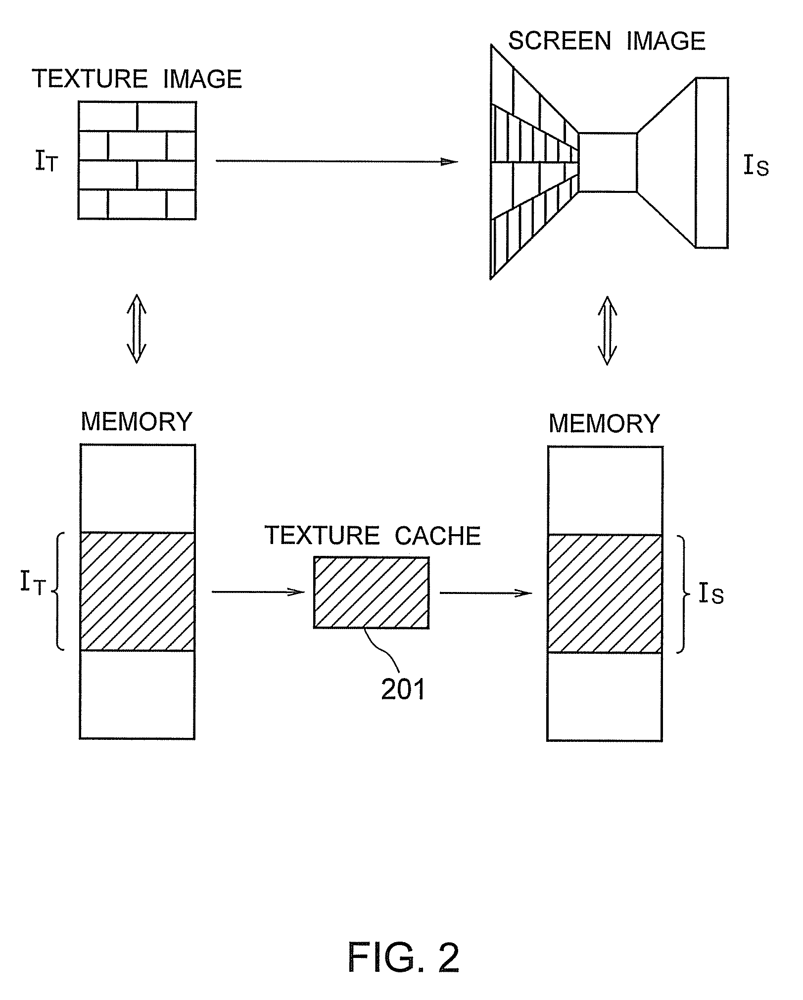
[0022]As shown in FIG. 2, the rendering apparatus 101 in FIG. 1 generates a screen image using a texture image. In FIG. 2, a screen image IS is generated from a texture image IT. In FIG. 2, the texture image IT and the screen image IS are stored in memories. When ...


PUM


Abstract

A computer graphics rendering apparatus according to an embodiment of the present invention generates a screen image, using plural texture images having different mipmap levels. The apparatus generates a normalized texture coordinate of a texture image, generates, from the normalized texture coordinate of the texture image, a texel coordinate of a texel in the texture image, according to a mipmap level of the texture image, and generates, regarding an image block in the texture image, an index value indicating a cache line corresponding to the image block, using a texel coordinate of a texel in the image block. The apparatus generates the index value such that index values of image blocks in the same position are different, between two texture images having mipmap levels adjacent to each other.

Description

CROSS REFERENCE TO RELATED APPLICATION[0001]This application is based upon and claims the benefit of priority from the prior Japanese Patent Application No. 2007-272488, filed on Oct. 19, 2007, the entire contents of which are incorporated herein by reference.BACKGROUND OF THE INVENTION[0002]1. Field of the Invention[0003]The present invention relates to a computer graphics rendering apparatus and a computer graphics rendering method.[0004]2. Background Art[0005]In the field of computer graphics, a method called texture mapping is widely known. In the texture mapping, it is possible to give texture to an object in an image, by pasting a texture image on the surface of the object. In the texture mapping, in order to realize an increase in speed of image processing, plural texture images having different resolutions are often used to represent the texture. Each of the texture images is called mipmap. The level of the resolution of each texture image is represented by a number called a...

Claims


Application Information

Patent Timeline
Patent Type & Authority Patents(United States)
IPC IPC(8): G09G5/00G06K9/36G06T11/40G06K9/40G06T15/04
CPCG06T15/04
Inventor TAKEMOTO, TAKASHI
Owner KK TOSHIBA
Why Eureka
Try Eureka