Eureka AIR delivers breakthrough ideas for toughest innovation challenges, trusted by R&D personnel around the world.

Image forming apparatus having a transferring member

a technology of transferring member and forming apparatus, which is applied in the direction of electrographic process apparatus, instruments, optics, etc., can solve the problems of generating image deficit, image deficit, and remarkably appearing image deficit, so as to avoid a toner image deficit and suppress the leading end of the recording material

Inactive Publication Date: 2012-03-06
CANON KK
View PDF25 Cites 2 Cited by
  • Summary
  • Abstract
  • Description
  • Claims
  • Application Information

AI Technical Summary

Benefits of technology

[0005]An object of the present invention is to suppress a leading end of a recording material from removing a toner image on a toner image bearing member, thereby avoiding a deficit of the toner image.

Problems solved by technology

Further, removal of the toner image by the leading end portion of the recording material generates an image deficit.
This image deficit hardly occurs when a sufficient margin is assured at an edge on the leading end side of the recording material, but this image deficit remarkably appears when a margin is small or when an image without a margin is formed.

Method used


Image

  • Image forming apparatus having a transferring member
  • Image forming apparatus having a transferring member
  • Image forming apparatus having a transferring member

Examples


first embodiment

[0020]A preferred embodiment according to the present invention will now be described hereinafter in detail with reference to the accompanying drawings. However, dimensions, materials, shapes, relative arrangements and others of constituent components described in the following embodiment should be appropriately changed based on a configuration or various kinds of conditions of an apparatus to which the present invention is applied, and a scope of the present invention is not restricted thereto unless a specific description is given in particular.

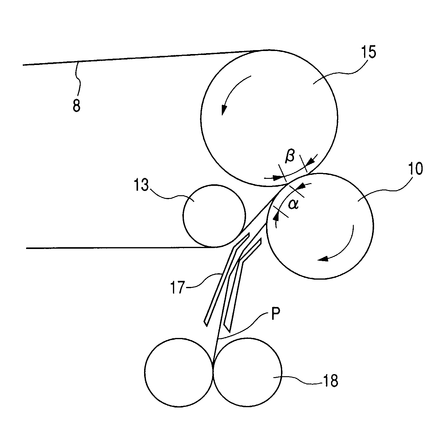
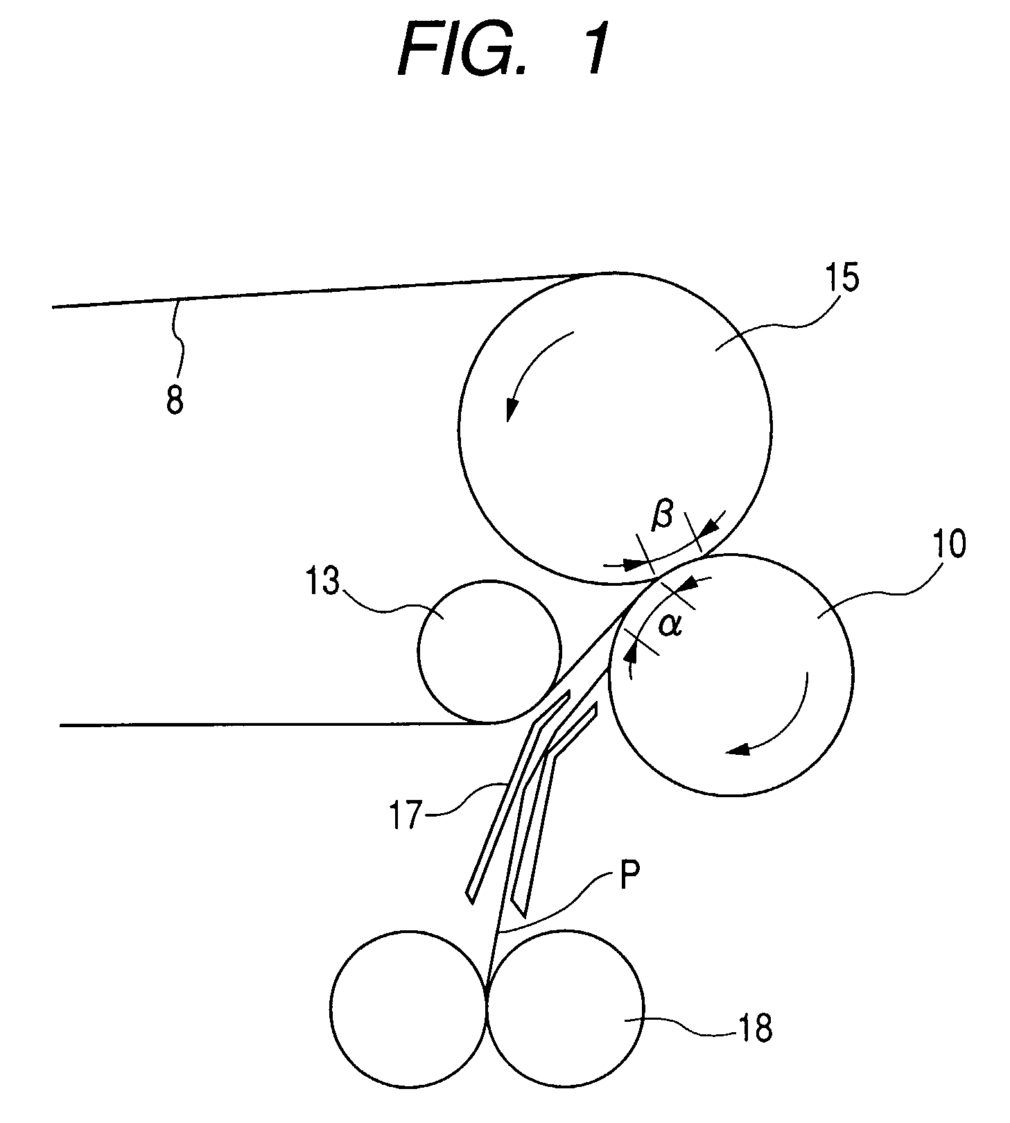
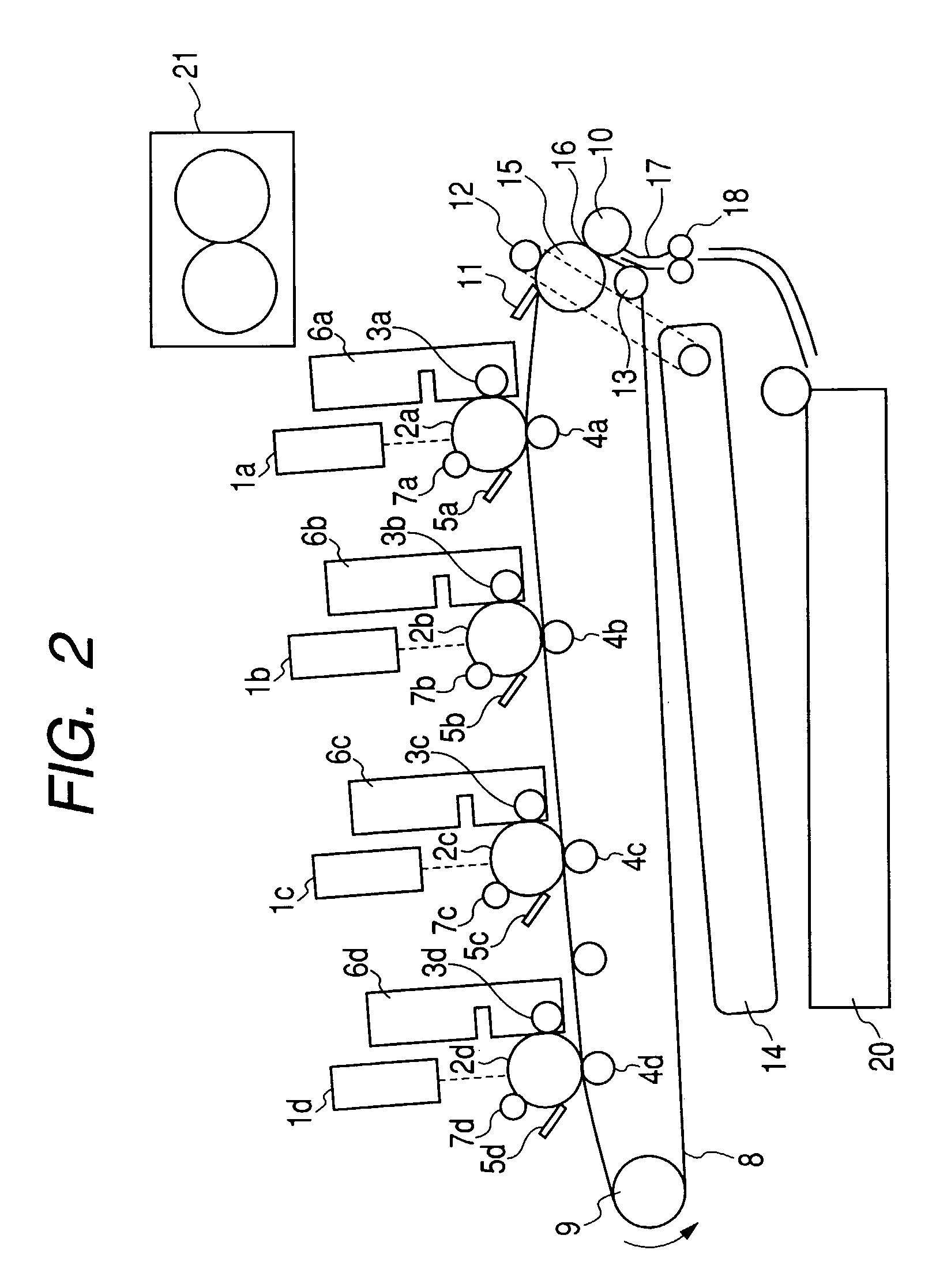
[0021]A description will be given as to an image forming apparatus according to a first embodiment of the present invention with reference to FIGS. 1, 2, 3 and 4. FIG. 2 is an outline configuration of a color image forming apparatus using an intermediate transfer mode according to the first embodiment.

[0022]In the color image forming apparatus adopting the intermediate transfer mode shown in FIG. 2, toner images having various colors are fo...

second embodiment

[0048]An image forming apparatus according to a second embodiment will now be described. It is to be noted that an outline structure of the entire image forming apparatus is substantially the same as that in the foregoing embodiment, and hence a description will be given on a structure different from the first embodiment. The structure having the elastic member consisting of the three-layered configuration on the cored bar as the secondary transfer roller formed of two or more layers has been described in the first embodiment, but a description will be given as to an example where the secondary transfer roller has a two-layered configuration in the second embodiment. A configuration and a material of the secondary transfer roller will now be described.

[0049]As shown in FIG. 4B, the secondary transfer roller according to this embodiment has a two-layered configuration, and a layer other than a surface layer is an elastic member whose hardness is not greater than 45° in terms of the A...

third embodiment

[0057]An image forming apparatus according to a third embodiment will now be described with reference to FIG. 5. FIG. 5 is a cross-sectional view showing a configuration around a secondary transfer portion. It is to be noted that an outline structure of the entire image forming apparatus is substantially the same as those of the foregoing embodiments, and hence a description will be given as to a configuration different from that in the first embodiment.

[0058]The image forming apparatus according to this embodiment has a “borderless image forming mode” which is a mode of forming a toner image without a margin on a recording material P.

[0059]In the image forming apparatus according to this embodiment, a toner image which is 3 mm larger than a size of the recording material in front-to-back and left-to-right directions was formed on an intermediate transfer belt 8 in such a manner that the toner image can be formed to reach an edge of the recording material P even in a state where a c...


PUM


Abstract

The image forming apparatus has a configuration in which a secondary transfer roller guides a leading end of a recording material which enters a secondary transfer nip to be led to the secondary transfer nip and the leading end of the recording material is prevented from coming into contact with a toner image on an intermediate transferring member before the recording material enters the secondary transfer nip. Further, in the image forming apparatus, a surface of a transfer roller is smoothened so that the leading end of the recording material is guided to the secondary transfer nip without being caught. As a result, the present invention is intended to prevent the leading end of the recording material which enters the secondary transfer nip from distorting the toner image on the intermediate transferring member.

Description

TECHNICAL FIELD[0001]The present invention relates to an image forming apparatus which transfers a toner image borne on an image bearing member onto a recording material.BACKGROUND ART[0002]As a conventional electrophotographic technology, there is a technology which inserts a recording material between an image bearing member bearing a toner image thereon and a transfer roller and transfers the toner image on the image bearing member onto the recording material.[0003]In this technology, U.S. Pat. No. 6,516,179 discloses how a recording material enters a transfer nip. An image forming apparatus described in this U.S. Pat. No. 6,516,179 has a guide member which guides the recording material toward a secondary transfer nip portion of an intermediate transfer belt. A leading end of the recording material is first brought into contact with the intermediate transfer belt by this guide member so that the recording material advances toward the secondary transfer nip along the intermediate ...

Claims


Application Information

Patent Timeline
Patent Type & Authority Patents(United States)
IPC IPC(8): G03G15/16
CPCG03G15/1685G03G15/6558G03G15/1665G03G2215/1614G03G2215/1652G03G2215/00409G03G15/02G03G15/16
Inventor SUZUKI, AKIMICHI
Owner CANON KK
Why Eureka
Eureka Blog
Learn More