Electrical power outlet

a technology of electrical power outlet and power outlet, which is applied in the direction of coupling device connection, connection contact member material, coupling protective earth/shielding arrangement, etc., can solve the problems of poor contact between the terminals and adversely affect the electrical conducting function of the power outlet, so as to avoid the risk of electric shock, prevent accidental touching of the exposed portions, and increase the contact stability

Active Publication Date: 2012-03-13
FURUTECH CO LTD
View PDF53 Cites 11 Cited by
  • Summary
  • Abstract
  • Description
  • Claims
  • Application Information

AI Technical Summary

Benefits of technology

[0006]In view of the above drawbacks of the prior art, an objective of the present invention is to provide a power outlet that can prevent accidental contact of the outlet by a user so as to significantly lower the risk of electric shock.
[0007]Another object of the present invention is to provide a power outlet so as to increase the contact stability between the terminals of a power line and the conductive terminals of the power outlet.
[0008]According to the above and other objectives, the present invention provides a power outlet, which comprises: a base having conductive terminals for electrically connecting to terminals of a power line, the conductive terminals being partially exposed from the base and a pair of first guiding portions arranged in parallel to each other being disposed on each side of the base exposing the conductive terminals; and sliding covers each having second guiding portions capable of sliding with and engaging with the corresponding first guiding portions so as to allow the sliding covers to slide relative to the base of the power outlet, thereby shielding the exposed portions of the conductive terminals.
[0012]Therefore, the power outlet of the present invention comprises a base and sliding covers. The base has conductive terminals disposed therein for electrical connecting to terminals of a power line. The conductive terminals are partially exposed from the base, and a pair of guiding portions arranged in parallel to each other is disposed on each side of the base exposing the conductive terminals. Each of the sliding covers has second guiding portions capable of slidingly engaging with the corresponding first guiding portions so as to allow the sliding covers to slide relative to the base, thereby shielding the exposed portions of the conductive terminals and preventing accidental touching of the exposed portions of the conductive terminals by a user so as to avoid the risk of electric shock.
[0013]The power outlet further comprises fastening boards with a concave portion. Each of the conductive terminals has a protruding portion corresponding to the concave portion. Through engagement of the protruding portions of the conductive terminals and the concave portions of the fastening boards, the contact area between the terminals of the power line and the conductive terminals is increased so as to prevent the terminals of the power line from releasing from the power outlet and increase the contact stability between the terminals of the power line and the conductive terminals of the power outlet.

Problems solved by technology

However, the protruding portions 211 are easy deformed under an external force, which reduces the contact area between the protruding portions 211 and the terminal 31 of the power line 3 and can even cause the terminal 31 to detach from the protruding portions 211, thereby leading to poor contact between the terminal 31 and the conductive terminal 1 and adversely affect the electrical conducting function of the power outlet.

Method used


Image

  • Electrical power outlet
  • Electrical power outlet
  • Electrical power outlet

Examples


Embodiment Construction

[0020]The following illustrative embodiments are provided to illustrate the disclosure of the present invention and its advantages, these and other advantages and effects being readily apparent to those in the art after reading this specification.

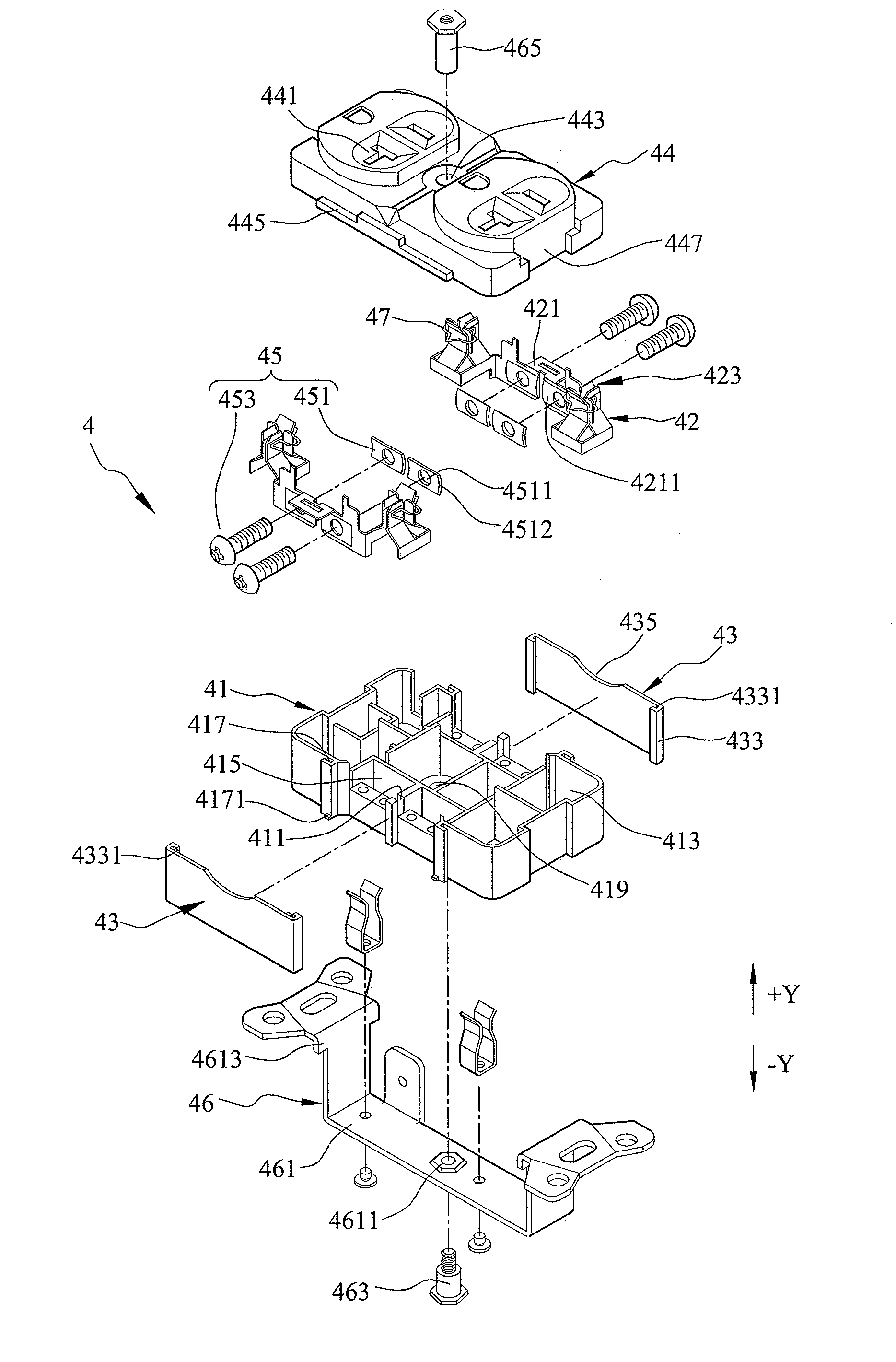
[0021]FIGS. 3 and 4 show an exploded view and a partially assembled view of a power outlet according to an embodiment of the present invention. Referring to FIGS. 3 and 4, the power outlet 4 comprises a base 41, conductive terminals 42, sliding covers 43, a cover body 44, locking units 45 and an elastic unit 46. It should be noted that the shape and number of the above-described components can be varied according to the practical needs and are not limited to those shown in the drawings.

[0022]The conductive terminals 42 are disposed in the base 41 for electrically connecting to terminals 51 of a power line 5. Therein, the conductive terminals 42 are partially exposed from the base 41, and a pair of first guiding portions 417 arranged in para...


PUM


Abstract

A power outlet includes a base and sliding covers. The base has conductive terminals for electrically connecting to terminals of a power line. The conductive terminals are partially exposed from the base and a pair of first guiding portions arranged in parallel to each other is disposed on each side of the base exposing the conductive terminals. Each of the sliding covers has second guiding portions capable of sliding with and engaging with the corresponding first guiding portions so as to allow the sliding covers to slide relative to the base, thereby shielding the exposed portions of the conductive terminals and preventing accidental touching of the exposed portions of the conductive terminals by a user and thus avoiding the risk of electric shock.

Description

BACKGROUND OF THE INVENTION[0001]1. Field of the Invention[0002]The present invention relates generally to power outlets, and, more particularly, to a power outlet capable of preventing accidental touching of the conductive terminals thereof, so as to significantly lower the risk of electric shock.[0003]2. Description of Related Art[0004]A power outlet, as shown in FIGS. 1 and 2 (PRIOR ART), generally has conductive terminals 1 disposed therein. Each of the conductive terminals 1 has a screw hole 11 and is covered by a fastening board 21. The fastening board 21 has an opening 213 formed therein corresponding in position to the screw hole 11 and a plurality of protruding portions 211 formed on the outward side thereof by pressing and facing towards the corresponding conductive terminal 1. The protruding portions 211 are used for pressing and covering a terminal 31 of a power line 3. A screw 23 is passed through the opening 213 of the fastening board 21 to engage with the screw hole 1...

Claims


Application Information

Patent Timeline
Patent Type & Authority Patents(United States)
IPC IPC(8): H01R4/66
CPCH01R4/44H01R13/447H01R25/006
Inventor NISHIMURA, YOJI
Owner FURUTECH CO LTD
Why Eureka
Try Eureka