

Remediation of functional cardiac mitral valve regurgitation
a functional cardiac mitral valve and regurgitation technology, applied in the field ofchronic cardiomyopathy, can solve the problems of increased risk of thromboembolism, increased patient mortality rate, and increased risk of cardiac function deterioration, so as to reduce the risk of thromboembolism and cardiac functional mitral valve regurgitation
Inactive Publication Date: 2012-03-13
COLORADO STATE UNIVERSITY
View PDF6 Cites 7 Cited by
- Summary
- Abstract
- Description
- Claims
- Application Information
AI Technical Summary
Benefits of technology
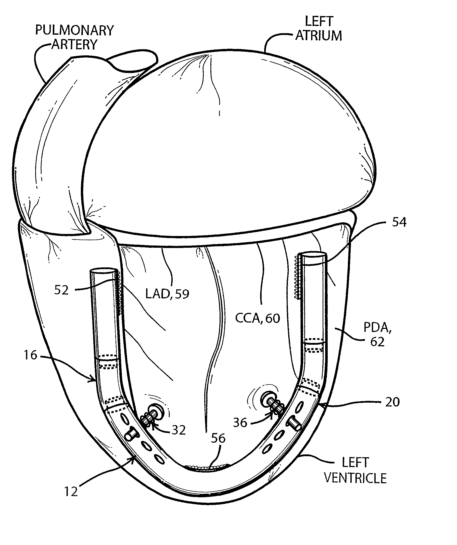
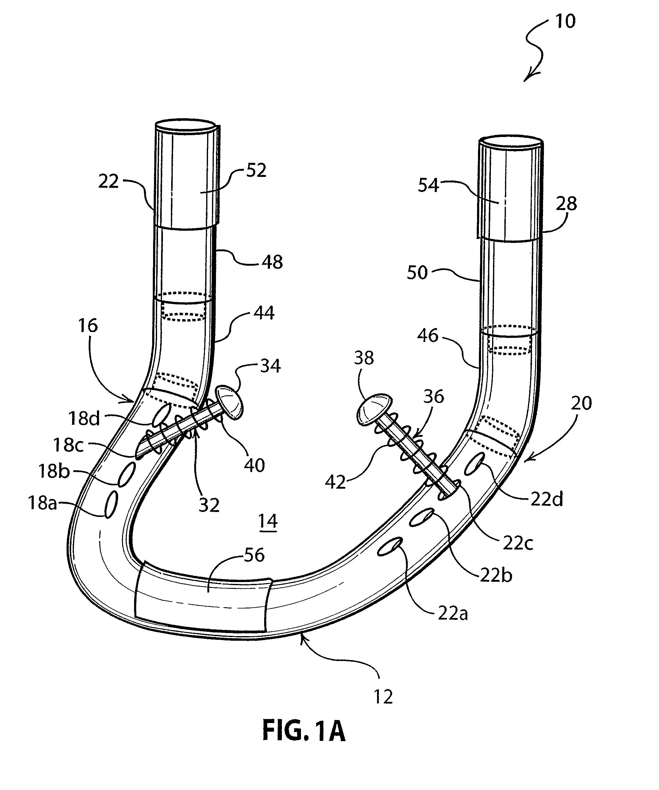
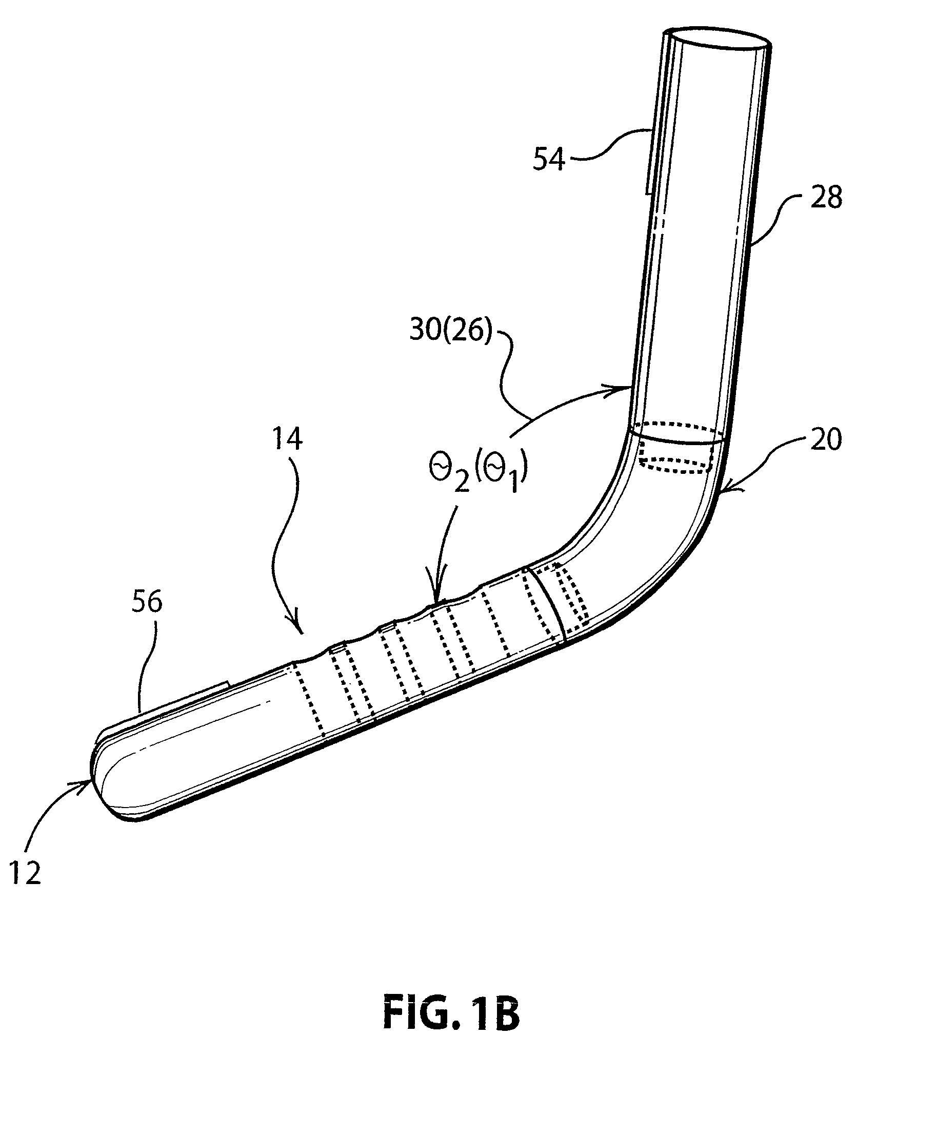
[0012]To achieve the foregoing and other objects, and in accordance with the purposes of the present invention, as embodied and broadly described herein, the apparatus adapted for external attachment to the left ventricle of a heart for remediating mitral valve regurgitation, hereof, includes: a U-shaped member having a planar portion, a first leg having at least one first hole therethrough, and a second leg parallel to the first leg having at least one second hole therethrough, the first leg having a portion thereof directed out of the planar portion at a first chosen angle and the second leg having a portion thereof directed out of the planar portion at a second chosen angle on the same side thereof as the out-of-plane portion of the first leg; a first rod having an enlarged portion at one end thereof adapted to slidably move in one of the at least one holes through the first leg; a second rod having an enlarged portion at one end thereof adapted to slidably move in one of the at least one second holes through the second leg; a first spring disposed between the end of the first rod bearing the enlarged portion and the first leg, for spring-loading the first rod; and a second spring disposed between the end of the second rod bearing the enlarged portion and the second leg, for spring-loading the second rod, wherein the enlarged portion of the first rod and the enlarged portion of the second rod provide a force against the left ventricle effective for reducing mitral valve regurgitation when the apparatus is attached to the left ventricle of a heart.
Problems solved by technology
However, this procedure requires cardiopulmonary bypass which results in a high mortality rate for patients.
Additionally, undersized annuloplasty does not treat the underlying problem of tethering on the mitral valve and sphericity of the heart, and places the patient at greater risk for further heart dilation and deterioration of cardiac function.
Since the device is in contact with blood within the heart, risk of thromboembolism is significantly increased.
Method used
View moreImage
Smart ImageViewing Examples

Examples
example
[0032]The device of the present invention was surgically implanted in 4 healthy dogs without heart failure. The stainless steel (311L) device was disposed on the left ventricle, and the support rods were placed against the base of the papillary muscles. The surgery was well tolerated by the dogs, with normal recovery and only minor arrhythmias post operatively which resolved after 2 weeks of treatment. No pleural effusion or infection was observed. There was no negative effect on cardiac function or myocardial blood flow after 10 weeks, and no ischemia was observed in the myocardium.
Login to View More PUM
 Abstract
A dynamic device for reducing functional mitral regurgitation is described. The device is disposed externally to the heart and effectively acts as a splint for reducing further dilation of the heart in patients diagnosed with cardiomyopathy, and for reducing tethering of the papillary muscle on the mitral valve. The device does not require cardiopulmonary bypass for its installation since it is attached to the outside of the left ventricle, thereby reducing surgical risk, and is not exposed to the patient's blood once installed, thereby reducing the risk of thromboembolic disease.
Description
CROSS-REFERENCE[0001]This application is the U.S. National Stage patent application of International Application No. PCT / US2006 / 034389, filed on Sep. 1, 2006, which claims the benefit under 35 U.S.C. section 119 (e) of U.S. Provisional Application 60 / 717,911 filed on Sep. 16, 2005, both of which are hereby incorporated by reference herein.FIELD OF THE INVENTION[0002]The present invention relates generally to chronic cardiomyopathy and, more particularly to the use of a dynamic device, external to the heart, for remediation of functional mitral valve regurgitation.BACKGROUND OF THE INVENTION[0003]Functional mitral regurgitation is believed to result from the absence of coaptation of the mitral valve leaflets without any mitral valve disease. It is a risk factor of dilated cardiomyopathy and ischemic cardiomyopathy as a consequence of ventricular remodeling and dilation of the valvular annulus, and / or papillary muscle dysfunction. Modification of the geometry of the left ventricle by ...
Claims
Login to View More Application Information
Patent Timeline
 Patent Type & AuthorityPatents(United States)
IPC IPC(8): A61N1/362
CPCA61F2/2481A61F2/2442
InventorMONNET, ERICORTON, E. CHRISTOPHERJAMES, SUSAN P.ORDWAY, KYLE GARRETTORDWAY, LEGAL REPRESENTATIVE, JOHN
OwnerCOLORADO STATE UNIVERSITY