Static eliminator and discharge electrode unit built therein

a technology of removing electrodes and discharge electrodes, which is applied in the direction of electrostatic charges, emergency protective arrangement details, and arrangements responsive to excess voltage, etc., can solve the problem of ions not easily flying in the direction, and achieve the effect of strengthening the electric field and increasing the efficiency of static elimination

Active Publication Date: 2012-03-13
KEYENCE
View PDF7 Cites 17 Cited by
  • Summary
  • Abstract
  • Description
  • Claims
  • Application Information

AI Technical Summary

Benefits of technology

[0007]An object of the present invention is to provide a static eliminator capable of weakening an electric field between a discharge electrode and a ground electrode to generate a strong electric field between the discharge electrode and a workpiece, so as to direct more ions in the direction where electric elimination is to be performed.
[0009]As thus described, burying the ground electrode plate in the insulating synthetic resin material can weaken the electric field between the ground electrode plate and the discharge electrode more than conventionally, it is thereby possible to relatively strengthen the electric field between the discharge electrode and a workpiece and hence increase the static elimination efficiency. Further, burying the ground electrode member in the insulating synthetic resin material constituting the bottom section where the discharge electrodes of the static eliminator are arrayed can design a static eliminator without considering surface discharge between the discharge electrode and the ground electrode member.

Problems solved by technology

There has thus been a problem in that the ions do not easily fly in the direction where static estimation to be performed.

Method used


Image

  • Static eliminator and discharge electrode unit built therein
  • Static eliminator and discharge electrode unit built therein
  • Static eliminator and discharge electrode unit built therein

Examples


Embodiment Construction

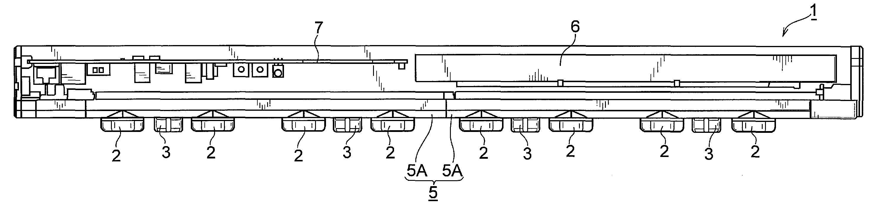
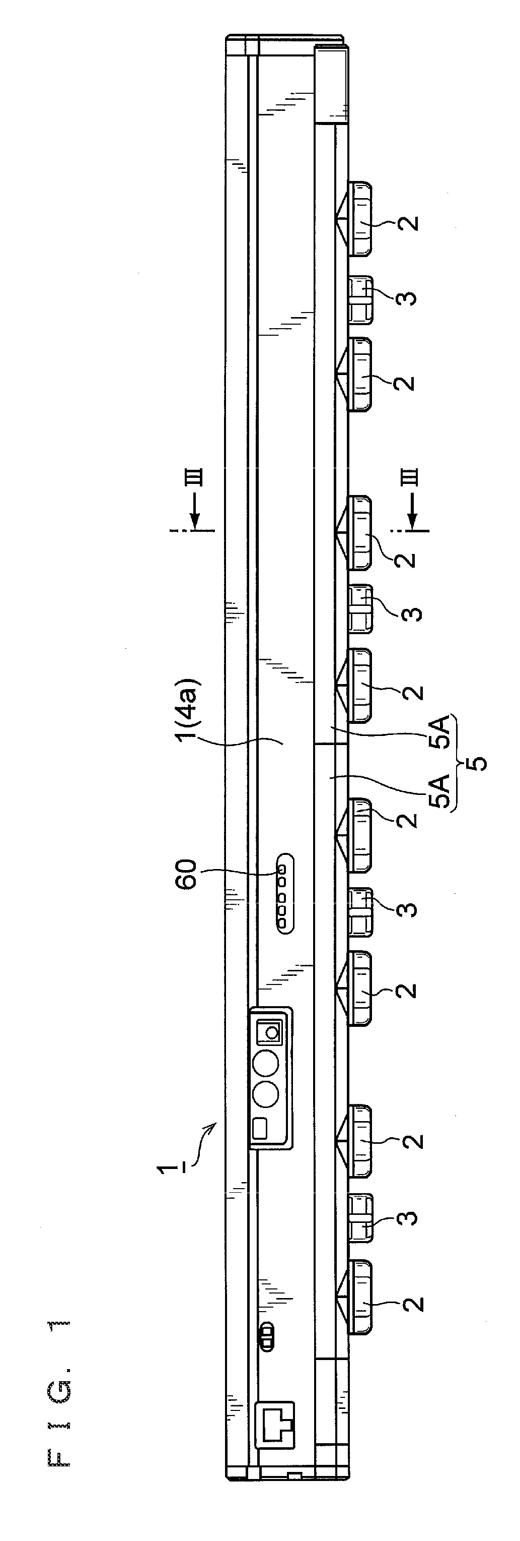
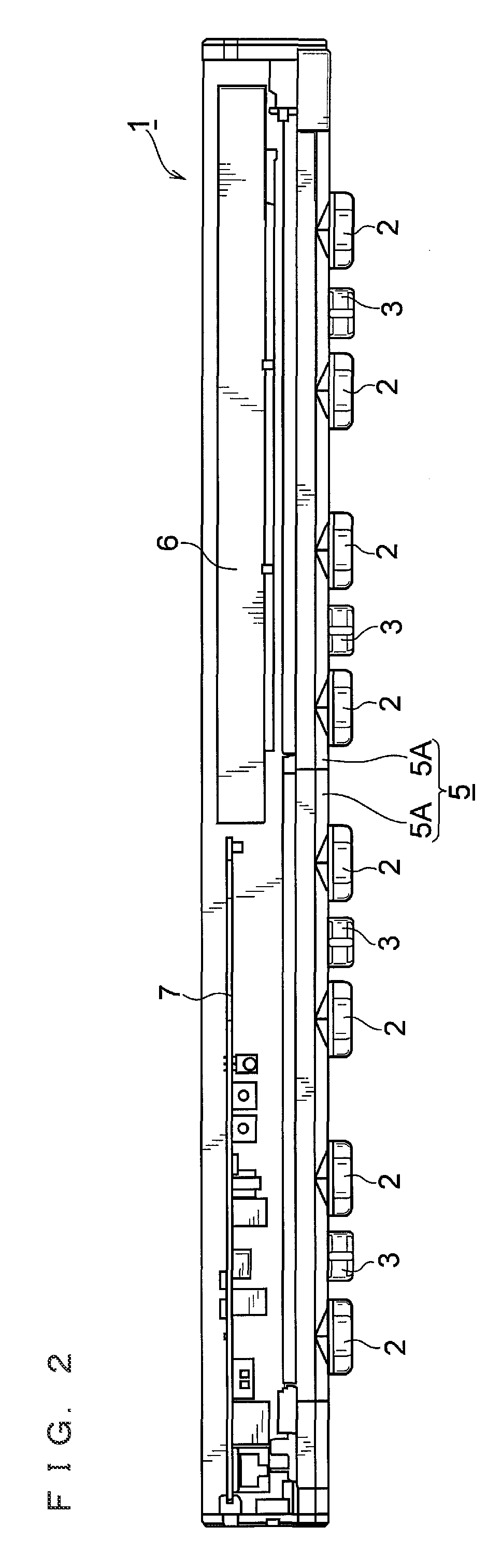
[0030]An embodiment of the present invention will be described in detail below with reference to the accompanying drawings. FIG. 1 is a side view of a static eliminator of the embodiment. In a static eliminator 1, eight main discharge electrode units 2 and four additional discharge electrode units 3 are mounted in a plurality of number in a longitudinally spaced condition on the bottom surface of a case 1a with a long external outline. It is to be noted that the four additional discharge electrode units 3 are attached and detached according to the user's option, and the configuration of this additional discharge electrode unit 3 is approximately equal to a basic configuration of the main discharge electrode unit 2. The difference between the main discharge electrode unit 2 and the additional discharge electrode unit 3 will be described later.

[0031]The outer case 4 for covering the upper half of the static eliminator 1 has a closed-top open-end cross-sectionally inverted U shape with...


PUM


Abstract

There is provided a static eliminator capable of weakening an electric field between a discharge electrode and a ground electrode, to generate a strong electric field between the discharge electrode and a workpiece, in which a first-stage circumferential chamber, a second-stage circumferential chamber and a first gas pool are arrayed in series along the longitudinal direction of a discharge electrode, the first gas pool is disposed in the mode of diametrically overlapping a gas outflow channel for shielding located on the inner circumferential side of the first gas pool, a gas is supplied to the first gas pool through the chambers disposed at multi-stages by means of the circumferentially spaced multi-stage orifices (the first and second chases), a ground electrode plate member in plate shape is buried in an insulating resin member on the bottom surface side of the half base in a position as high as where the first gas pool is located, and the ground electrode plate member includes a circular ring section concentric with the discharge electrode.

Description

CROSS-REFERENCE TO RELATED APPLICATIONS[0001]The present application claims foreign priority based on Japanese Patent Application No. 2007-341093, filed Dec. 28, 2007, the contents of which is incorporated herein by reference.BACKGROUND OF THE INVENTION[0002]1. Field of the Invention[0003]The present invention relates to a static eliminator used for eliminating static electricity of a workpiece, and a discharge electrode unit built therein.[0004]2. Description of the Related Art[0005]For the purpose of eliminating static electricity of a workpiece, a corona discharge type static eliminator has often been used. Typically, in a static eliminator having a long bar shape, a plurality of discharge electrodes are mounted in a longitudinally spaced condition, and a high voltage is applied to these discharge electrodes to generate an electric field between the discharge electrodes and the workpiece and thereby to apply ions to the workpiece so that static electricity of the workpiece is eli...

Claims


Application Information

Patent Timeline
Patent Type & Authority Patents(United States)
IPC IPC(8): H05F3/00
CPCH01T23/00H05F3/04
Inventor FUKAI, KOJIIMATAKA, TEPPEI
Owner KEYENCE
Why Eureka
Try Eureka