Eureka AIR delivers breakthrough ideas for toughest innovation challenges, trusted by R&D personnel around the world.

Tuner and Demodulating Unit Thereof

Inactive Publication Date: 2008-09-25
LG INNOTEK CO LTD
View PDF3 Cites 2 Cited by
  • Summary
  • Abstract
  • Description
  • Claims
  • Application Information

AI Technical Summary

Benefits of technology

[0016]According to the present invention, the video and sound quality in a selected channel improves and especially in the US channel 6.
[0017]Moreover, there is advantage of preventing the deterioration of the video and sound quality in a TV by effectively eliminating a frequency band signal acting as noise in a video baseband.
[0018]Furthermore, there is advantage of improving noise elimination efficiency in a selected channel by eliminating an FM radio frequency band signal and other adjacent channel frequency band signals in a video baseband.

Problems solved by technology

However, when the FM radio frequency signal of a high frequency band is eliminated, the video and sound frequency signals of the US channel 6 adjacent to the FM radio frequency signal is undesirably weakened.

Method used


Image

  • Tuner and Demodulating Unit Thereof
  • Tuner and Demodulating Unit Thereof
  • Tuner and Demodulating Unit Thereof

Examples


first embodiment

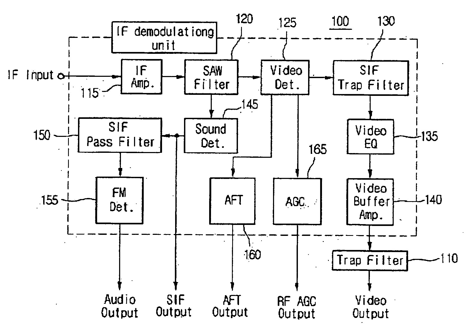
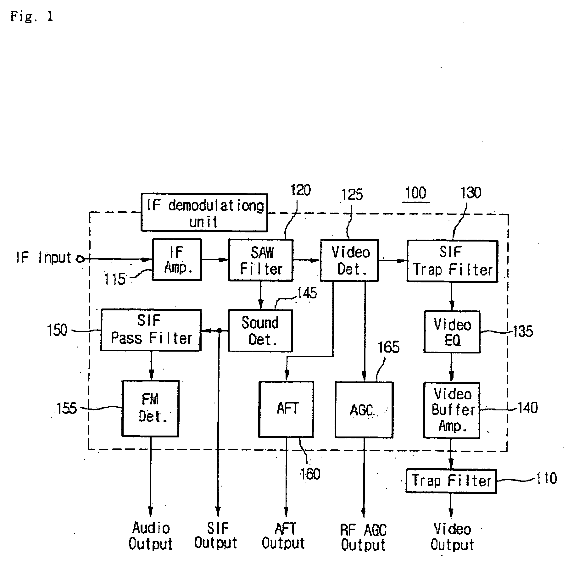
[0023]FIG. 1 is a block diagram illustrating a demodulating unit of a tuner according to the invention.

[0024]Referring to FIG. 1, a tuner includes an RF processing unit (not shown) for converting an RF signal into an IF signal, and an IF demodulating unit 100 for demodulating the IF signal. The signals demodulated by the IF demodulating unit are provided to respective elements of a TV to allow the television to operate.

[0025]The IF demodulating unit 100 includes a surface acoustic wave (SAW) filter 120 for selecting only a signal of a specific frequency band among IF signals received from the high frequency process unit, and an IF amplifier 115 for amplifying the selected IF signal.

[0026]Signals divided by the SAW filter are inputted to a sound detector 145 and a video detector 125 respectively. By this configuration, IF sound and video signals are demodulated while passing through a sound signal processing line and a video signal processing line respectively.

[0027]A sound intermedi...

second embodiment

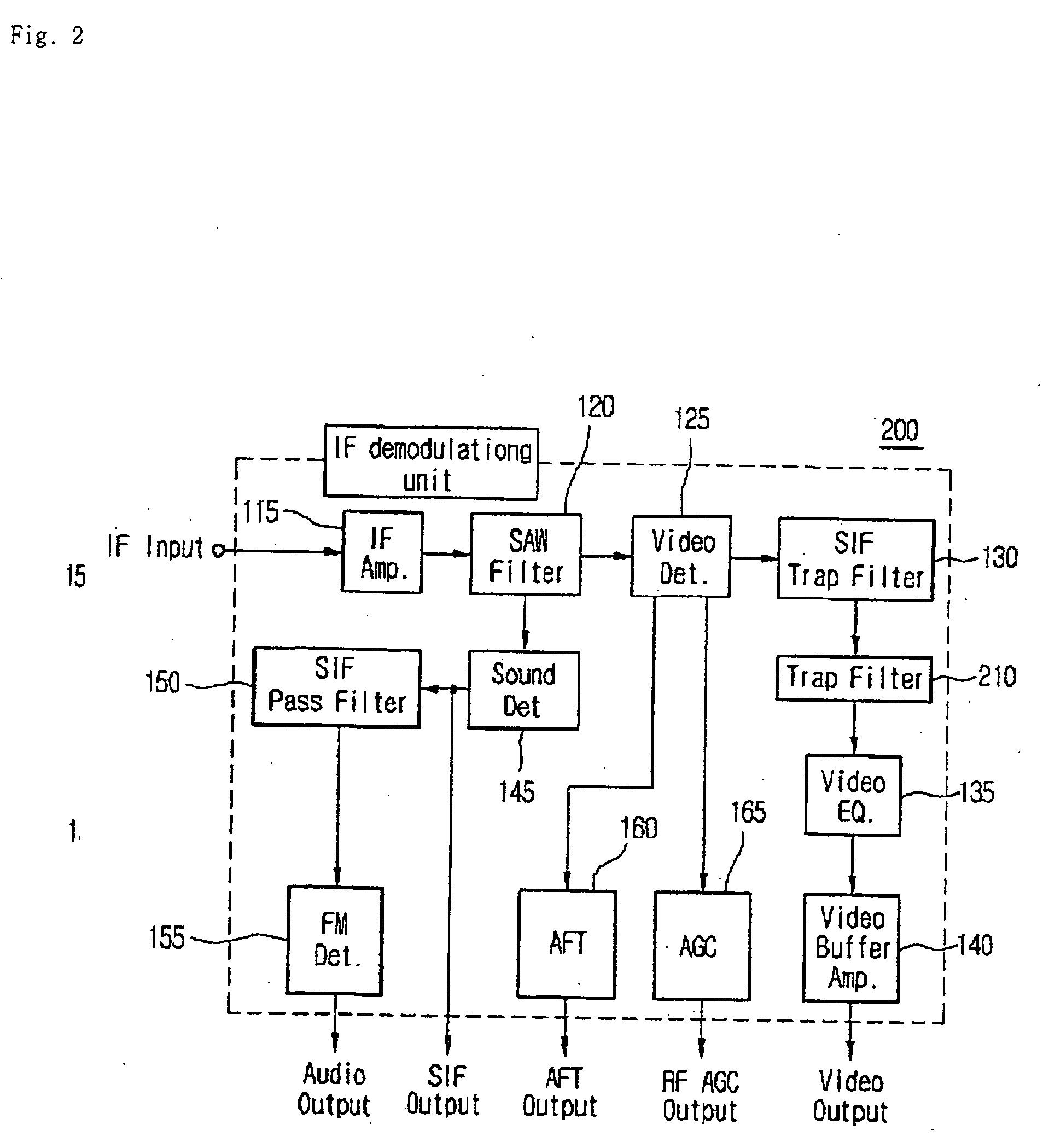
[0044]FIG. 2 is a block diagram illustrating a demodulating unit of a tuner according to the invention.

[0045]The second embodiment is identical to the first embodiment with the exception of the installation location of a trap filter.

[0046]Referring to FIG. 2, a trap filter 210 for eliminating a FM radio signal is disposed between an SIF trap filter 130 and a video equalizer 135 to in a demodulating unit of a tuner 200.

[0047]In case of the second embodiment, it is predictable to have same effect like the first embodiment. Moreover, the trap filter can be conveniently installed in the demodulating unit when manufacturing the demodulating unit.


PUM


Abstract

A tuner and a demodulating unit thereof are provided. A trap filter for a specific frequency is installed in the IF demodulating unit so as to eliminate a frequency signal acting as a beat component.

Description

TECHNICAL FIELD[0001]The present invention relates to an intermediate frequency demodulating unit of a tuner, and more particularly, to a demodulating unit of a television tuner including a rejection circuit for effectively eliminating a frequency signal that acts as a beat component when a television image signal is demodulated.BACKGROUND ART[0002]In general, a tuner receives a radio frequency (RF) signal through an antenna, converts the RF signal into an intermediate frequency (IF) signal, detects the IF signal, separates the detected IF signal into a video signal and a sound signal, and outputs each signal. There is an advantage of improving frequency selectivity, reducing sensitivity for peripheral circuits and enhancing stability by additionally performing the IF conversion process during an operation of the tuner.[0003]A structure of a general tuner will be briefly described below. The general tuner includes an antenna, a mixer, and a local oscillator. A TV broadcasting system...

Claims


Application Information

Patent Timeline
IPC IPC(8): H03D99/00H03J3/00
CPCH04N5/455H03J3/00
Inventor LEE, HYE-RYUNG
Owner LG INNOTEK CO LTD
Why Eureka
Eureka Blog
Learn More