Height measurement in a perspective image

a perspective image and height measurement technology, applied in the field of data processing system, can solve the problems of two-dimensional images, inability to convey more than two dimensions of information such as width and depth, and two-dimensional images also present a perspective distortion

Active Publication Date: 2012-03-20
THE BOEING CO
View PDF6 Cites 51 Cited by
  • Summary
  • Abstract
  • Description
  • Claims
  • Application Information

AI Technical Summary

Problems solved by technology

Two-dimensional images, however, are unable to convey more than two dimensions of information such as width and depth.
Two-dimensional images also present a perspective distortion due to the means by which they were acquired.
One issue with this type of technique is that sufficiently accurate three-dimensional models of scenes may not be easy to obtain.
If a location on the surface of the scene cannot be measured for an elevation value or cannot be measured accurately, the corresponding value describing the element for that location is either missing or inaccurate.
This type of technique, however, is unable to capture small elevation details or some types of vertical features with accuracy.
The sharp discontinuities in the surface may cause dissimilarities in the stereo images that may defeat the stereo correlation process for that particular object.
Further, stereo imagery and the amount of data needed to retain the scene model for this technique may also result in these models having a lower spatial resolution for array locations.
As a result, these types of models do not provide an accurate representation of all features on a surface.
As a result, an image of the mountain with the tower cannot be used to obtain a measurement to identify a location of the top of the tower.
As a result, identifying locations in a scene corresponding to an image of the scene may be difficult to perform.
For example, if the feature is a tree, a building, or some other object not taken into account in the digital elevation model, the location of those objects cannot be accurately identified even with registration of the image to the digital elevation model.

Method used


Image

  • Height measurement in a perspective image
  • Height measurement in a perspective image
  • Height measurement in a perspective image

Examples


Embodiment Construction

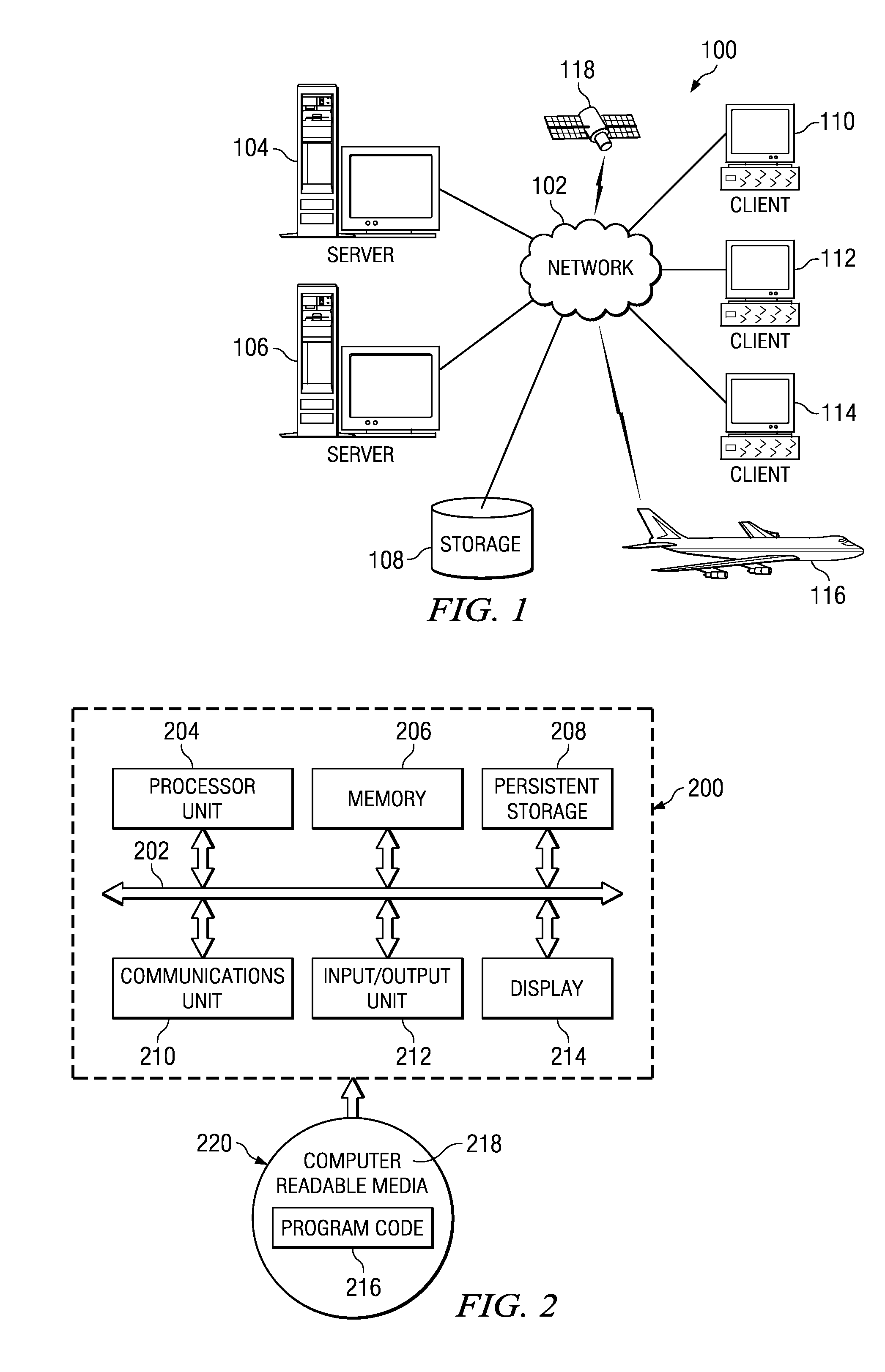
[0042]With reference now to the figures and in particular with reference to FIGS. 1-2, exemplary diagrams of data processing environments are provided in which the advantageous embodiments may be implemented. It should be appreciated that FIGS. 1-2 are only exemplary and are not intended to assert or imply any limitation with regard to the environments in which different embodiments may be implemented. Many modifications to the depicted environments may be made.

[0043]With reference now to the figures, FIG. 1 depicts a pictorial representation of a network of data processing systems in which the advantageous embodiments may be implemented. Network data processing system 100 is a network of computers in which embodiments may be implemented. Network data processing system 100 contains network 102, which is the medium used to provide communications links between various devices and computers connected together within network data processing system 100. Network 102 may include connection...


PUM


Abstract

A method, apparatus, and computer program product are present for identifying a location in a scene. An image of the scene is displayed on a display device. A cursor on the image is moved in relation to a number of corresponding directions in a model of the scene in response to a manipulation of a number of controls associated with the cursor. A base location in the scene is identified corresponding to a particular point in response to a user input selecting the particular point in the image. A selected point in the image is selected for the scene and a displacement of the selected point is identified from the base location in response to another user input occurring after an identification of the base location. An offset location in the scene is identified corresponding to the selected point in the image using the base location and the displacement.

Description

BACKGROUND INFORMATION[0001]1. Field[0002]The present disclosure relates generally to an improved data processing system and in particular, to a method and apparatus for processing data. Still more particularly, the present disclosure relates to a method, apparatus, and computer program product for measuring height in a perspective image.[0003]2. Background[0004]Images of a scene may be generated using various types of sensors. These sensors include, for example, forward looking infrared cameras, synthetic aperture radar systems, video cameras, and other suitable types of sensors. It may be desirable to make measurements of a feature in the image of a scene. Two-dimensional images, however, are unable to convey more than two dimensions of information such as width and depth.[0005]Two-dimensional images also present a perspective distortion due to the means by which they were acquired. For images formed using a lens, such as video cameras or forward looking infrared cameras, this dis...

Claims


Application Information

Patent Timeline
Patent Type & Authority Patents(United States)
IPC IPC(8): H04N7/18G06G5/00G06K9/32
CPCG06K9/00637G06K9/2081G06T17/05G06T2200/24G06V20/176G06V10/235
Inventor OLDROYD, LAWRENCE ANDREW
Owner THE BOEING CO
Why Eureka
Try Eureka