Detecting fluids in a wellbore

a technology of fluid detection and wellbore, which is applied in the direction of wellbore/well accessories, optical prospecting, instruments, etc., can solve the problems of reducing the hydrocarbon displacement efficiency of injected fluid, less than ideal sweep and production performance, and difficulty in short circuit analysis

Active Publication Date: 2012-03-27
OXY USA INC
View PDF17 Cites 44 Cited by
  • Summary
  • Abstract
  • Description
  • Claims
  • Application Information

AI Technical Summary

Benefits of technology

[0007]In certain implementations, the method may further include instigating a remedial action based at least in part on the quantification. Instigating a remedial action may include at least one of the following: isolating the first communication interval in the production wellbore from a remaining portion of the production wellbore; and substantially preventing the receipt of the second fluid at the production wellbore. In some implementations, isolating the first communication interval in the production wellbore from a remaining portion of the production wellbore may include inserting at least one packer into the production wellbore; setting the packer into the production wellbore proximate to the first communication interval in the production wellbore; and at least partially isolating the first communication interval from the remaining portion of the production wellbore with the packer.
[0017]Various implementations of a downhole fluid detector according to the present disclosure may include one or more of the following features. For example, the detector may allow identification of where fluids enter a wellbore. The detector may also allow identification of a source and / or path of communication between an injection well and a production well. The detector may also allow differentiation between the fluorescence of hydrocarbons entering a wellbore and the fluorescence of tracers / dyes injected into an offset injection well with the injected fluid used to displace hydrocarbons in enhanced recovery operations. As a further example, the downhole fluid detector may allow diagnostics to be performed on a producing well to determine which interval of a well is producing hydrocarbons and which interval is producing an injected fluid. The detector may thus indicate when and where remedial actions should be taken to correct short circuits between injectors and producers without damaging the hydrocarbon producing interval. Further, the detector may substantially prevent extensive cycling of the injected fluid, which may result in decreased loss of revenue and greater hydrocarbon recovery. Additionally, the downhole fluid detector may reduce the uncertainty of production profile analysis in mature hydrocarbon producing zones. The detector may also improve a success rate for “profile control” work involving shutting off an injectant (e.g., water, nitrogen, or gas) used in enhanced recovery operations.

Problems solved by technology

Areal interaction between injection and production wells are impacted by the heterogeneity of the rock, which can result in less than ideal sweep and production performance.
These short circuits typically reduce the hydrocarbon displacement efficiency of the injected fluid.
There may sometimes be difficulties with short circuit analysis.
For instance, multiple flow paths may exist between injection wells and production wells, each having a distinct response time and rate, which can overlap and confuse analysis of the production and injection responses.
In such cases, the injected fluids flow quickly from injector to producer contacting little oil, which consequently results in loss of revenue and, ultimately, lower hydrocarbon recovery.
Further, the detector may substantially prevent extensive cycling of the injected fluid, which may result in decreased loss of revenue and greater hydrocarbon recovery.

Method used


Image

  • Detecting fluids in a wellbore
  • Detecting fluids in a wellbore
  • Detecting fluids in a wellbore

Examples


Embodiment Construction

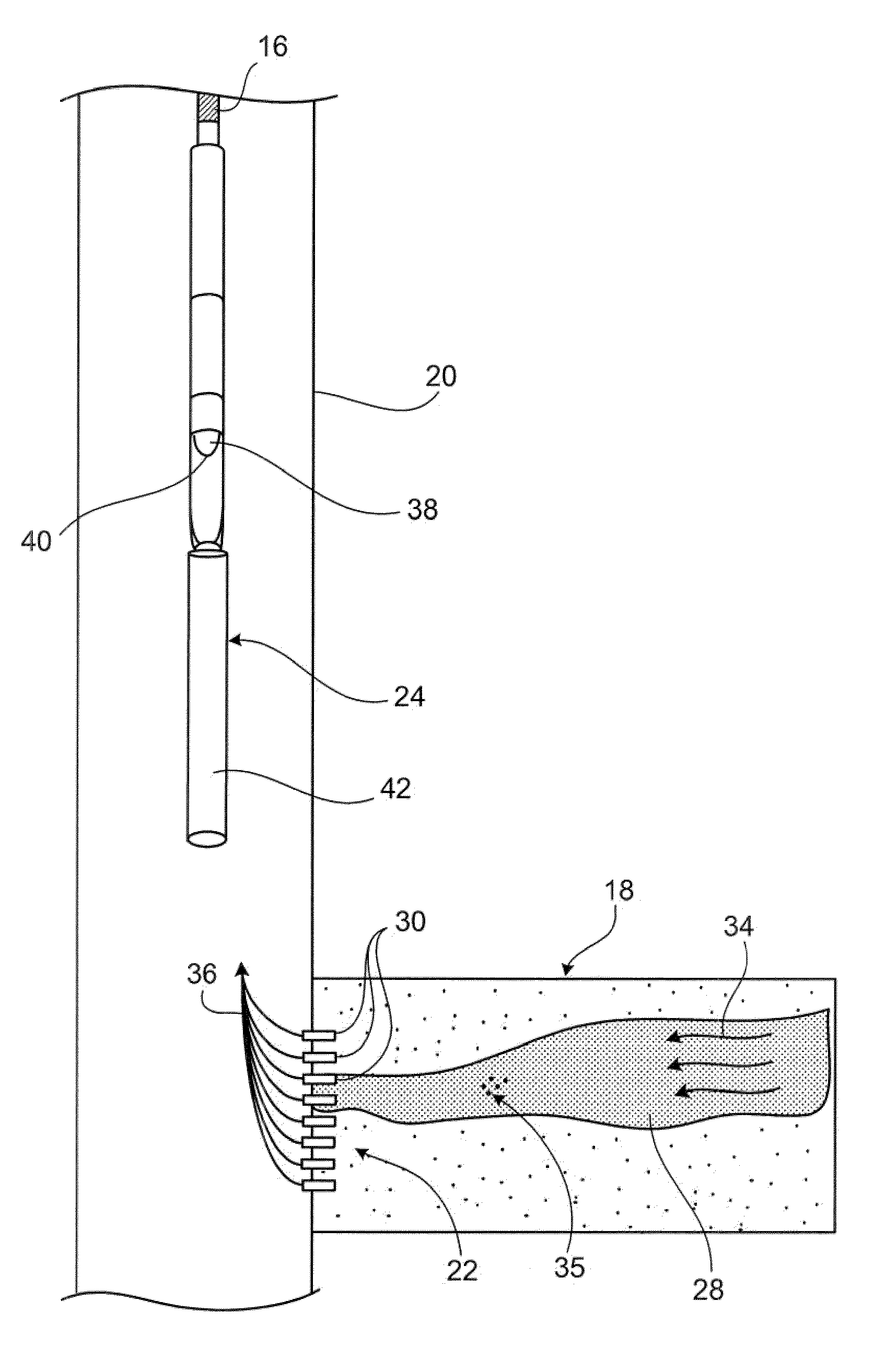
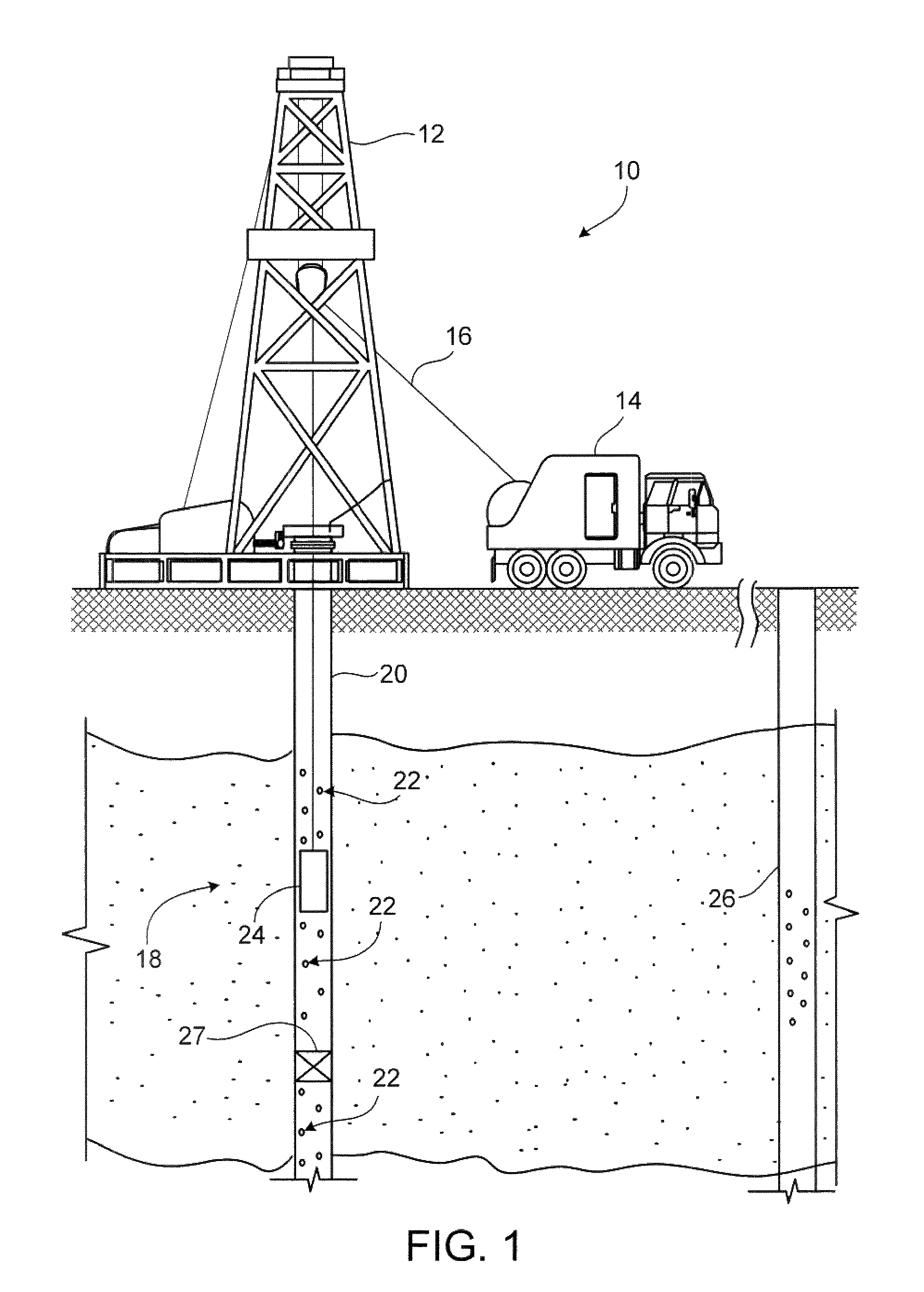
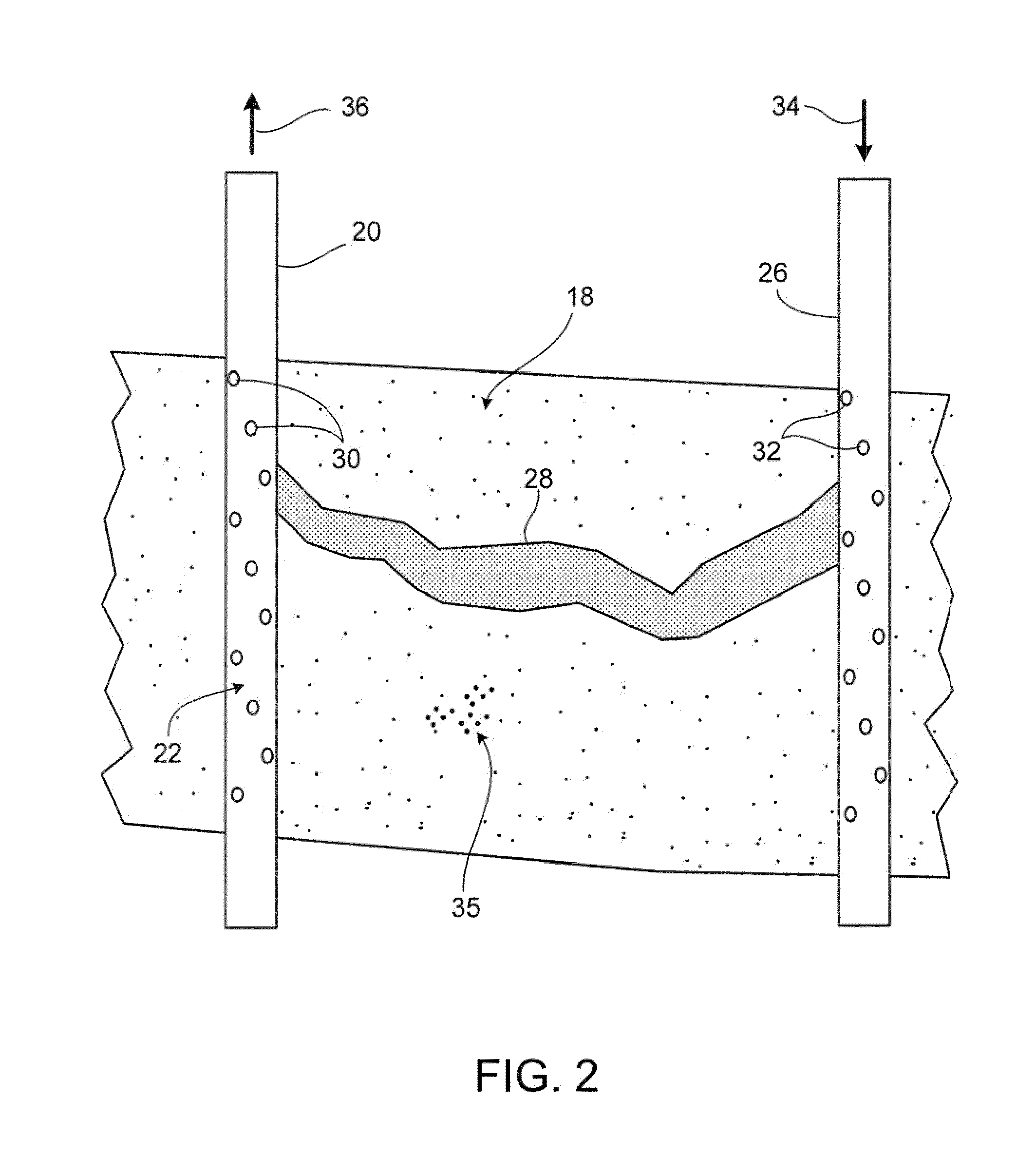
[0024]One implementation of a downhole fluid detector includes a visible spectrum light source and an ultraviolet light source along with an optical receiver that, when lowered into a production wellbore, can produce video and still images of a fluid entering a wellbore under both light spectrums. The downhole fluid detector may distinguish between the produced fluids by observed differences in the fluorescence of hydrocarbons entering the production wellbore and the fluorescence of a tracer injected with the injected fluid into an offset injection well. A quantification of the amount of hydrocarbons relative to the injected fluid being received at any particular communication interval, or production zone, of the wellbore may be performed. This quantification may help indicate when remedial action should be taken to correct “short circuits” between the injection well and the production well, as well as where within the producing well to minimize damage to other hydrocarbon-producing...


PUM


Abstract

In one general implementation, a method for identifying fluids in a wellbore includes generating light in a visible spectrum from a light source in a production wellbore; generating light in an ultraviolet spectrum from the light source in the production wellbore; receiving a first fluid in the production wellbore from a subterranean zone; receiving a second fluid in the production wellbore from the subterranean zone; capturing at least one image of a combined flow of the first fluid and the second fluid in at least one of the visible spectrum and the ultraviolet spectrum with an optical receiver in the production wellbore; and distinguishing, at least in part through the image, the first fluid from the second fluid in either or both the visible and ultraviolet spectrums.

Description

TECHNICAL BACKGROUND[0001]This disclosure relates to wellbore equipment and, more particularly, to downhole tools used for detecting fluids at a well site and in wellbores.BACKGROUND[0002]Secondary production of existing oil and gas wells may help increase the output of hydrocarbons (e.g., oil and gas) from a subterranean zone. Injection wells are drilled and used to introduce fluids into the subterranean zone into which a production well may be drilled. The injected fluids may increase or maintain hydrocarbon production from the production well. Areal interaction between injection and production wells are impacted by the heterogeneity of the rock, which can result in less than ideal sweep and production performance. For example, “short circuits” between injection wells and production wells may occur. In the present disclosure, a “short-circuit” may be any path that provides preferential flow to the injectant and allows communication between an injection well and a production well, ...

Claims


Application Information

Patent Timeline
Patent Type & Authority Patents(United States)
IPC IPC(8): E21B49/08G01V5/08
CPCG01V8/02E21B47/102E21B47/0002E21B47/002E21B47/113
Inventor HAMPTON, DAVID W.KRAMM, ROBERT C.
Owner OXY USA INC
Why Eureka
Try Eureka