Arrangement to detune a reception antenna in a local coil

a local coil and antenna technology, applied in the direction of magnetic measurements, instruments, measuring devices, etc., can solve the problems of mechanical defects at the respective plugs and individual cables, mechanically susceptible cable connections that are required for the feed of control signals for the active detuning circuit, and the difficulty of managing, so as to achieve less error-prone and less expenditure

Active Publication Date: 2011-12-27
SIEMENS HEALTHCARE GMBH
View PDF24 Cites 6 Cited by
  • Summary
  • Abstract
  • Description
  • Claims
  • Application Information

AI Technical Summary

Benefits of technology

[0025]An object of the present invention to provide, for a local coil whose received magnetic resonance signals are transmitted wirelessly for additional processing, an arrangement for detuning that is less error-prone with less expenditure.
[0026]This object is achieved by an arrangement according to the invention for detuning a reception antenna in a local coil having at least one reception antenna that is fashioned as a loop antenna and that ahs at least one first capacitance. Radio-frequency signals of a magnetic resonance examination are received by the reception antenna. A switchable detuning circuit contains the first capacitance a first inductance connected to an oscillating circuit. A reception device to receive a control signal is coupled with the oscillating circuit, and the reception device switches the oscillating circuit into a high-resistance state when a control signal is received. A receipt of a radio-frequency signal via the reception antenna is therefore prevented.
[0029]The active detuning foregoes a wired feed of control signals so that the previously necessary connection cables for control signal transmission are spared.
[0030]The activation or deactivation of the detuning circuit no longer ensues via cables and is therefore less error-prone.

Problems solved by technology

Due to this multiplicity of necessary cables, a cable bundle connected with the local coil is formed that is unwieldy and can be difficult to manage.
Due to the dimensions and the resulting weight, as well as the movement of the cable bundle, mechanical defects can occur at the respective plugs and at the individual cables.
The mechanically susceptible cable connections that are required for the feed of the control signals for the active detuning circuit still remain.

Method used


Image

  • Arrangement to detune a reception antenna in a local coil
  • Arrangement to detune a reception antenna in a local coil
  • Arrangement to detune a reception antenna in a local coil

Examples


first embodiment

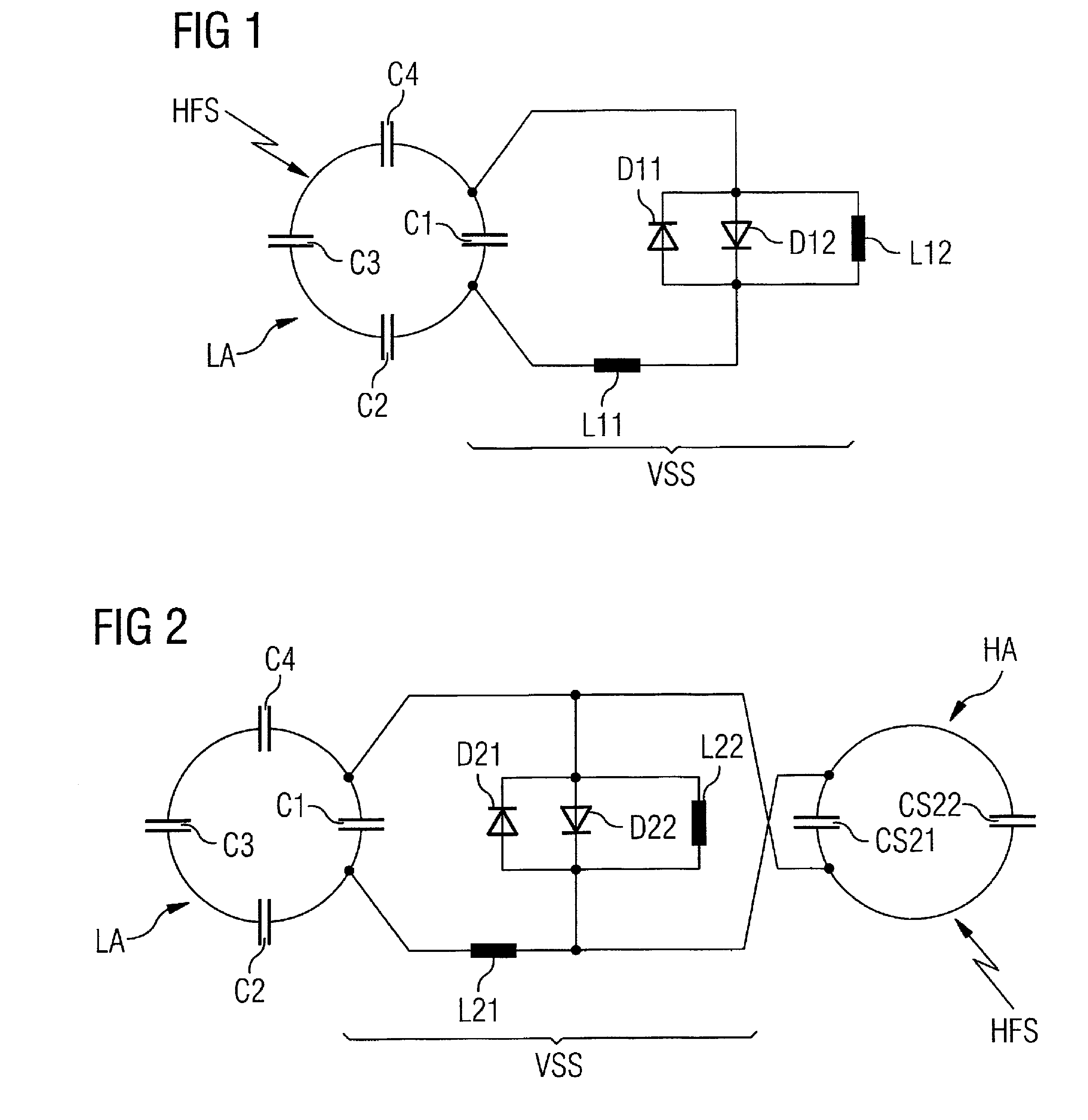
[0036]FIG. 1 shows the arrangement according to the invention with what is known as a loop antenna LA as a reception antenna.

[0037]The reception antenna LA shows four capacitances C1 through C4 that are fashioned to shorten the reception antenna LA.

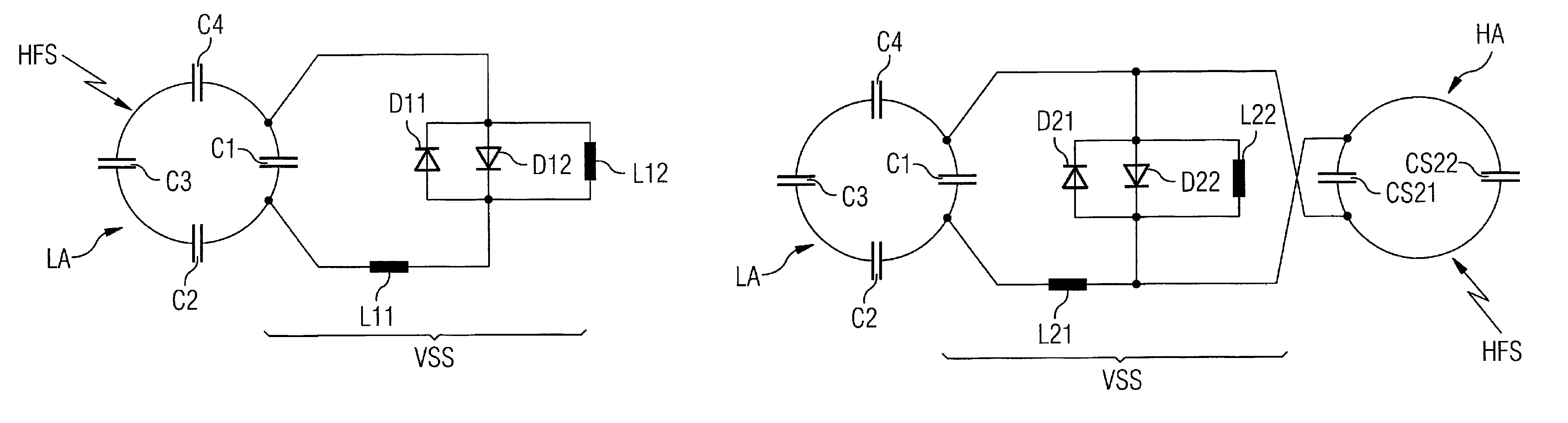
[0038]A first capacitor C1 together with a first inductance L11 forms a block circuit that, together with a first diode D11, a second diode D12 and a second inductance L12, forms a detuning circuit VSS.

[0039]The first diode D11, the second diode D12 as well as the second inductance L12 are connected in parallel to one another, wherein the two diodes D11, D12 are additionally connected or, respectively, arranged inverse to one another.

[0040]This parallel circuit is connected on the input side with a first end of the first capacitor C1 while the parallel circuit is connected at the output side via the first inductance L11 with a second end of the first capacitor C1.

[0041]In a patient examination, magnetic resonance signals with a bandwidth ...

second embodiment

[0047]FIG. 2 shows the arrangement according to the invention, with a loop antenna LA as a reception antenna.

[0048]The reception antenna LA shows four capacitances C1 through C4 that are fashioned to shorten the reception antenna LA.

[0049]A first capacitor C1 together with a first inductance L21 forms a block circuit that, together with a first diode D21, a second diode D22 and a second inductance L22, forms a detuning circuit VSS.

[0050]The first diode D21, the second diode D22 as well as the second inductance L22 are thereby connected in parallel to one another, wherein the two diodes D21, D22 are additionally connected or, respectively, arranged inverse to one another.

[0051]This parallel circuit is connected on the input side with a first end of the first capacitor C1 while the parallel circuit is connected at the output side via the first inductance L21 with a second end of the first capacitor C1.

[0052]In a patient examination, magnetic resonance signals with a bandwidth BMR are ...

third embodiment

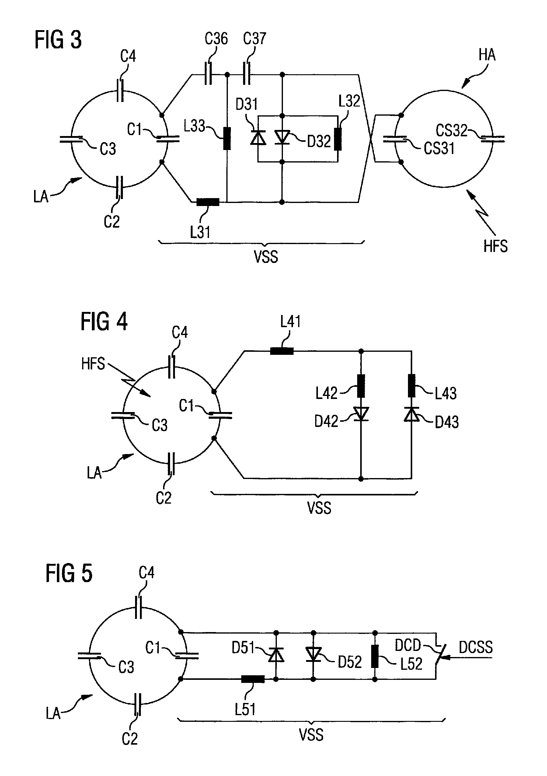
[0062]FIG. 3 shows a variant (relative to FIG. 2) of the arrangement according to the invention as the invention.

[0063]Corresponding to FIG. 2, a first capacitor C1 of the reception antenna LA forms a detuning circuit VSS together with a first inductance L31, a first diode D31, a second diode D32 and a second inductance L32.

[0064]The first diode D31, the second diode D32 as well as the second inductance L32 are thereby connected in parallel to one another, wherein the two diodes D31, D32 are additionally connected or, respectively, arranged inverse to one another.

[0065]This parallel circuit is connected on the input side via a λ / 4 phase shifter with a first end of the first capacitor C1, while the parallel circuit is connected at the output side via the λ / 4 phase shifter and via the first inductance L31 with a second end of the first capacitor C1.

[0066]The λ / 4 phase shifter contains two capacitances C36 and C37 in a shunt arm in the form of a T-circuit as well as an inductance L33 i...


PUM


Abstract

An arrangement to detune a reception antenna in a local coil of a magnetic resonance system, with at least one reception antenna that is fashioned as a loop antenna and that has at least one first capacitance. Radio-frequency signals of a magnetic resonance examination are received via the reception antenna. A switchable detuning circuit contains the first capacitance connected to an oscillating circuit and a first inductance. A reception device to receive a control signal is coupled with the oscillating circuit. The reception device switches the oscillating circuit into a high-resistance state given a received control signal so that a receipt of a radio-frequency signal via the reception antenna is prevented. The reception device is fashioned to receive a wirelessly transmitted radio-frequency control signal. The radio-frequency control signal has a frequency that lies outside of the bandwidth of the radio-frequency signal used for magnetic resonance examination.

Description

BACKGROUND OF THE INVENTION[0001]1. Field of the Invention[0002]The present invention concerns an arrangement to detune a reception antenna in a local coil of the type employing a switchable tuning circuit.[0003]2. Description of the Prior Art[0004]In modern magnetic resonance systems, magnetic resonance examination signals are acquired with the use of local coils placed close to the patient.[0005]In addition to actual reception antennas (that are preferably fashioned as loop antennas), the local coil contains additional low-noise preamplifiers in order to be able to amplify the acquired magnetic resonance signals. The local coil additionally contains for each loop antenna, an associated active detuning circuit with which that reception antenna can be detuned during a transmission phase.[0006]During the transmission phase the detuning is necessary in order to prevent an unwanted inductive injection of strong currents (which could be generated in the reception antenna by a received t...

Claims


Application Information

Patent Timeline
Patent Type & Authority Patents(United States)
IPC IPC(8): G01V3/00
CPCG01R33/3692G01R33/3628G01R33/341
Inventor BIBER, STEPHANGREIM, HELMUTSTAPF, JOERG CHRISTOPHER
Owner SIEMENS HEALTHCARE GMBH
Why Eureka
Try Eureka