Eureka AIR delivers breakthrough ideas for toughest innovation challenges, trusted by R&D personnel around the world.

Biochip having an electode array on a substrate

a technology of electrode arrays and biochips, applied in the field of biochips having electrode arrays, can solve the problems of not being able to meet the needs of large-scale applications, requiring special training personnel to operate properly, and the equipment necessary for optical detection is relatively complicated and expensive, so as to achieve simplified and reliable arrangement, improve efficiency, and reduce error prone

Inactive Publication Date: 2006-05-18
ROBERT BOSCH GMBH
View PDF10 Cites 51 Cited by
  • Summary
  • Abstract
  • Description
  • Claims
  • Application Information

AI Technical Summary

Benefits of technology

[0007] The biochip according to the present invention has the advantage that it is easier to operate and less error-prone in comparison to the conventional biochips. In particular, the present invention provides for a simplified and reliable arrangement for contacting the numerous electrodes of the electrode array with an external electronic analysis system. Furthermore, the method according to the present invention makes it possible to manufacture the biochip in a simple and cost-effective manner.

Problems solved by technology

Although such optical methods exhibit a high sensitivity, they are not optimal for widespread mass application.
The equipment necessary for optical detection is relatively complicated and expensive, and to operate it properly requires specially trained personnel.
Moreover, it is typically heavy and is only able to be installed stationary in a lab.

Method used


Image

  • Biochip having an electode array on a substrate
  • Biochip having an electode array on a substrate
  • Biochip having an electode array on a substrate

Examples


Embodiment Construction

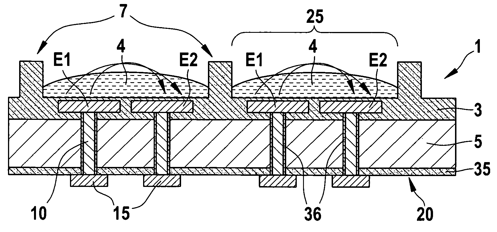
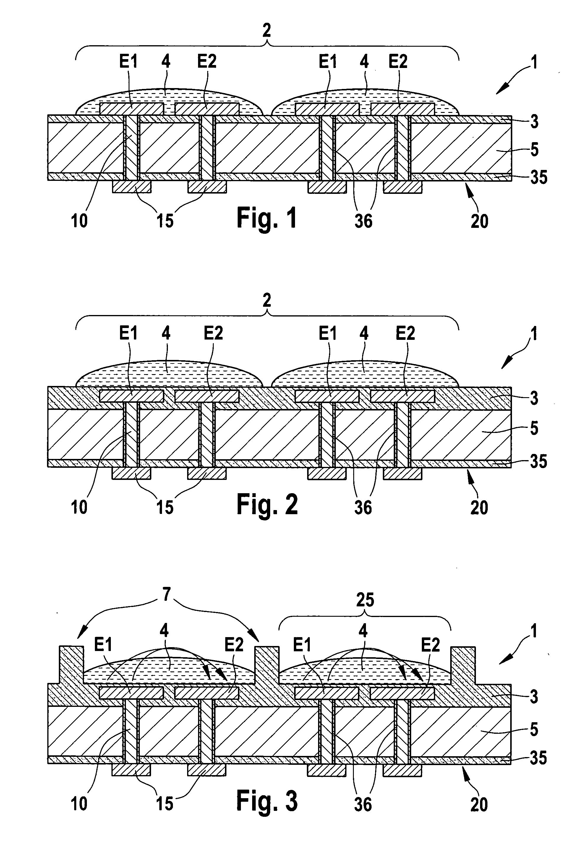
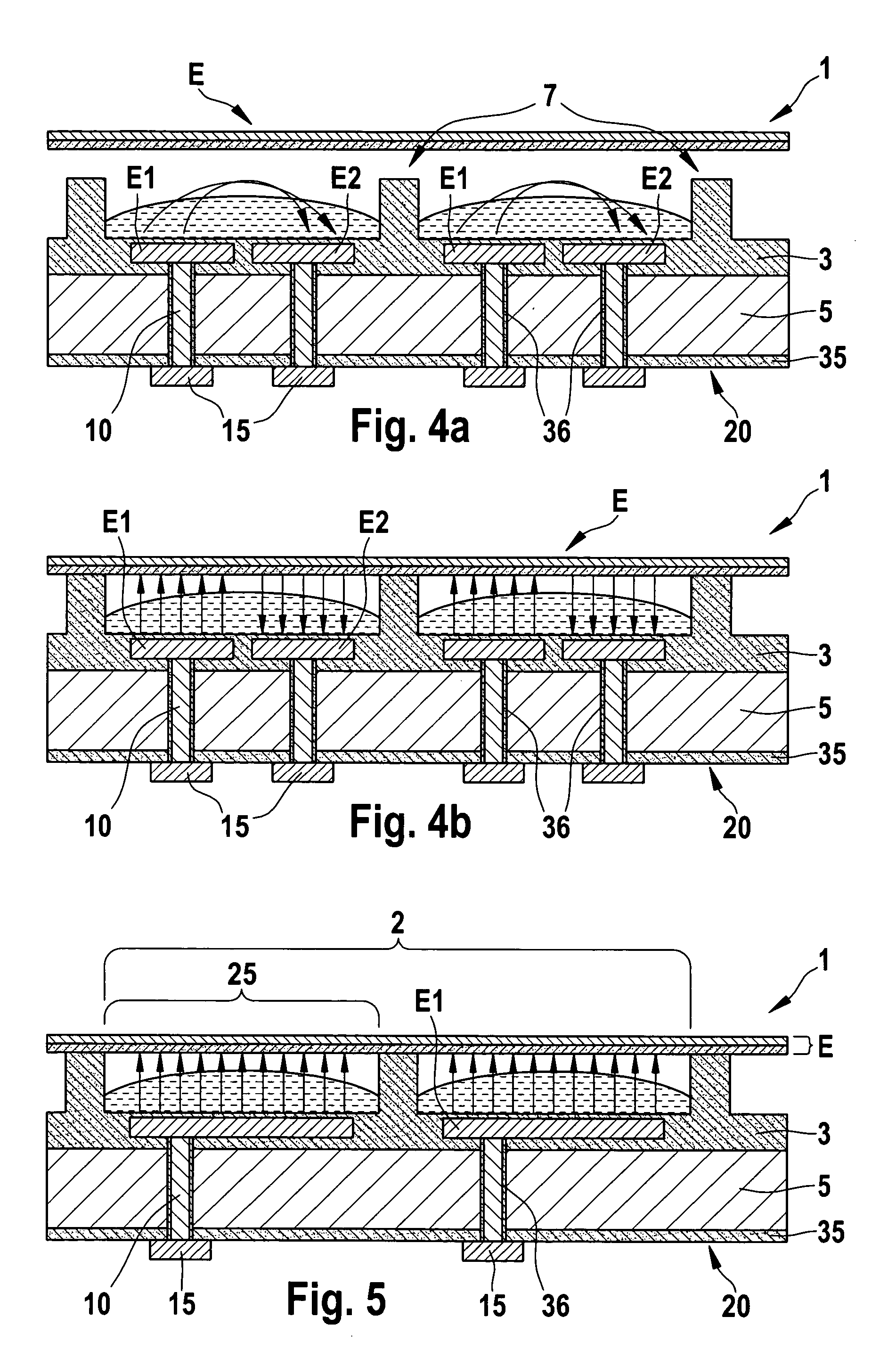
[0015] The structure of a biochip according to the present invention will be explained in connection with FIG. 1, which shows in a cross-sectional view a biochip 1 having an electrode array 2 on a substrate 5, i.e., a grid-shaped system of electrodes E1, E2 for electrically detecting biochemical molecules. While electrodes E1, E2 are made of gold, or aluminum, or another electrically conductive material, substrate 5 in FIG. 1 is made of silicon. A first insulating layer 3, e.g., Si-oxide, is situated for insulation between substrate 5 made of silicon and electrodes E1, E2. In contrast to the embodiments in the prior art, electrodes E1, E2 of electrode array 2 are each connected through substrate 5 to an electrically conductive contact surface 15 via an electrical conductor 10, contact surfaces 15 being situated on side 20 facing away from electrode array 2 and forming the outermost plane of biochip 1 on this side 20. This side 20, facing away from electrode array 2, is defined as th...


PUM

PropertyMeasurementUnit
electrically conductiveaaaaaaaaaa
elevationsaaaaaaaaaa
areaaaaaaaaaaa

Abstract

A biochip for electrical, e.g., capacitive, detection of biochemical molecules has an electrode array on a substrate, the electrodes of the electrode array being each connected through the substrate to an electrically conductive contact surface via an electrical conductor. The contact surfaces are situated on the side of the substrate facing away from the electrode array and form the outermost plane of the substrate on this side.

Description

FIELD OF THE INVENTION [0001] The present invention relates to a biochip having an electrode array on a substrate for electrically, e.g., capacitively, detecting biochemical molecules, and also relates to a method for manufacturing such a biochip and electrically contacting such a biochip to an electronic analysis system. BACKGROUND INFORMATION [0002] Optical methods, fluorescent methods in particular, are nowadays primarily used for detecting biochemical molecules. During a process known as dye marking, fluorescent molecules are chemically appended to the molecules to be detected, whereby the molecules to be detected are labeled with fluorescent molecules. If such molecules are irradiated with UV light or visible light, they absorb the energy from the light and get into an electronically excited state. Via one or multiple transitions from higher energy levels back to lower states, the molecules reach their electronic basic state where they emit the fluorescent light having a certai...

Claims


Application Information

Patent Timeline
Patent Type & Authority Applications(United States)
IPC IPC(8): C12M1/34G01N27/00
CPCB01L3/5085B01L3/5088B01L2300/0645B01L2300/0819G01N27/3276
Inventor LARMER, FRANZEISENSCHMID, HEINZSTUMBER, MICHAELROCZNIK, MARKOSCHOLTEN, DICK
Owner ROBERT BOSCH GMBH
Why Eureka
Eureka Blog
Learn More