

Phase current detector
- Summary
- Abstract
- Description
- Claims
- Application Information
AI Technical Summary
Benefits of technology
Problems solved by technology
Method used
Image

Examples
Embodiment Construction
[0099]Hereinafter, referring to the accompanying drawings, we explain a phase current detection apparatus of embodiments according to the present invention in detail.
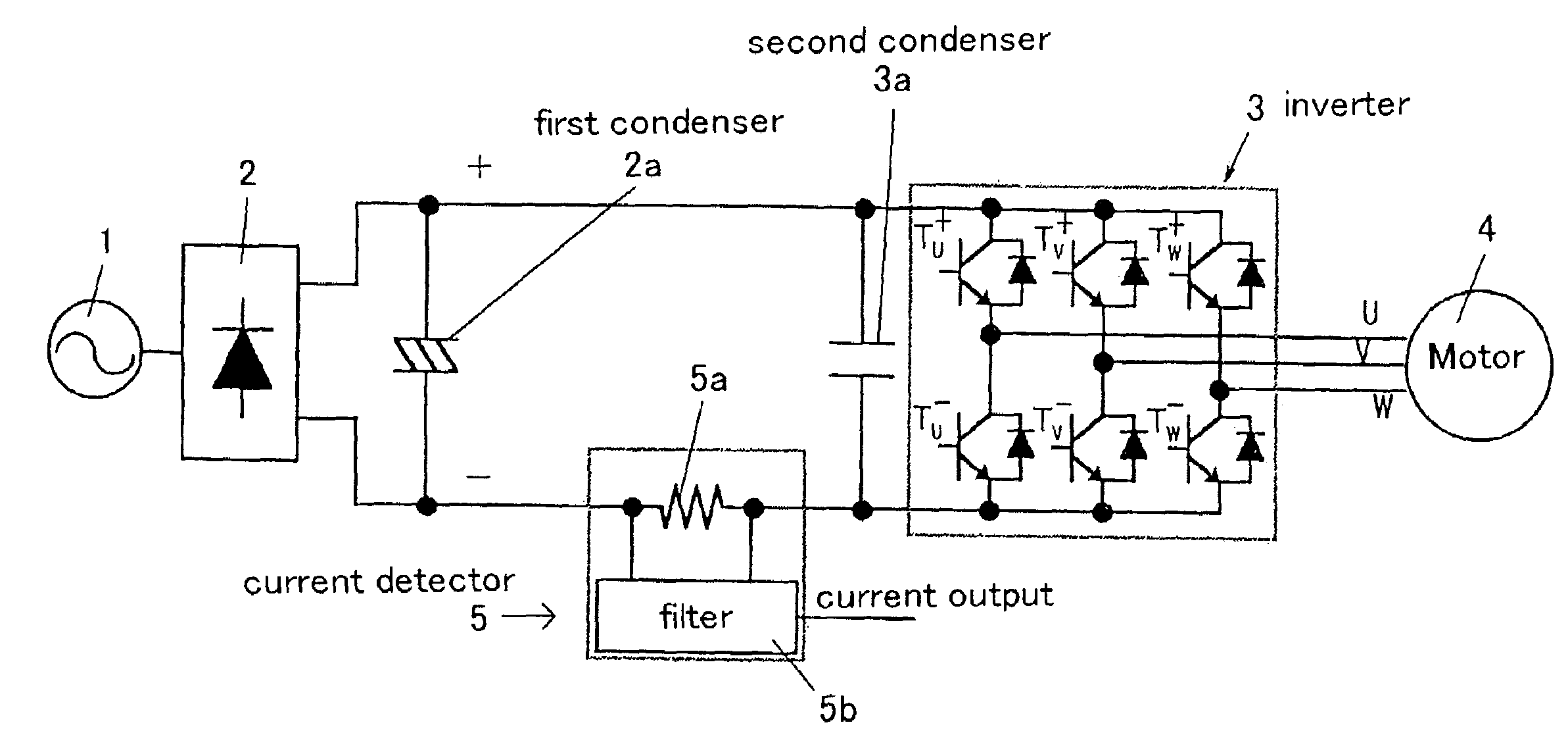
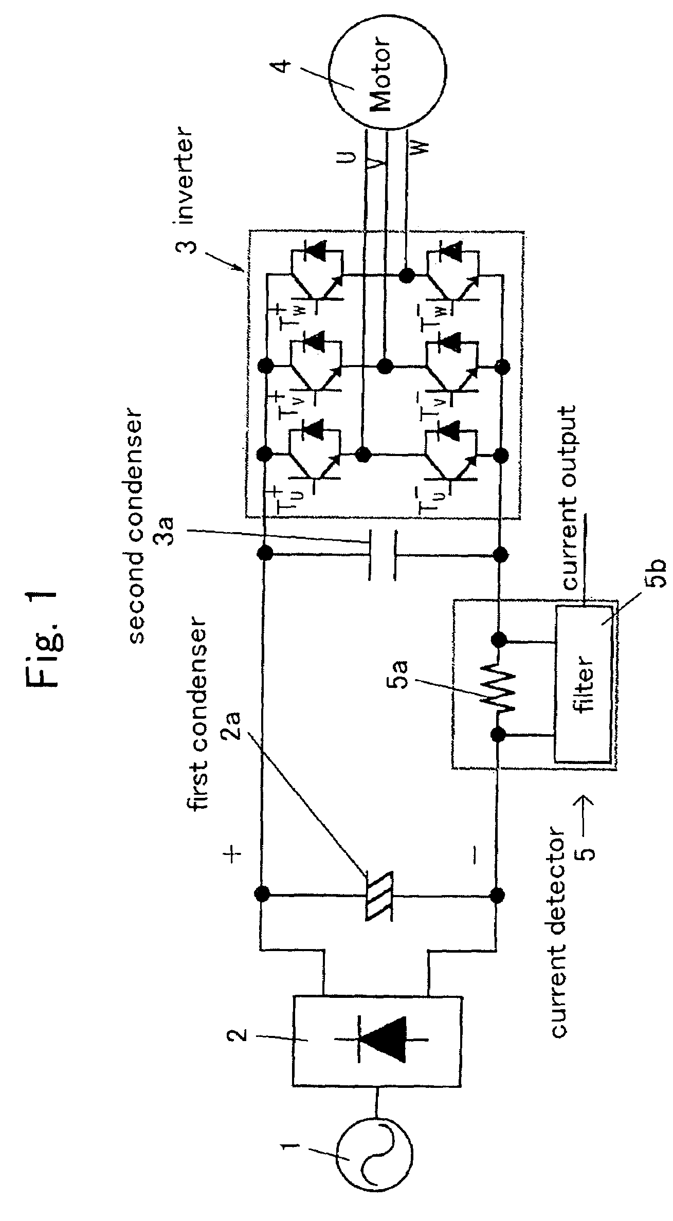
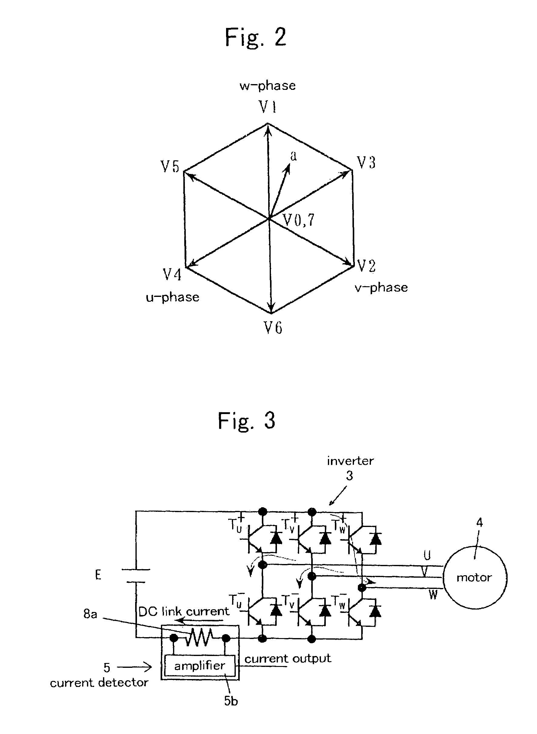
[0100]FIG. 1 is a diagram illustrating an arrangement of a motor driving apparatus using an inverter. FIG. 1 depicts relationships between an output voltage vector of the inverter (power devices) and switching condition of switching elements.
[0101]In FIG. 1, Tu, Tv, Tw represent switching elements of upper arms of u-phase, v-phase, and w-phase, respectively. Tu−, Tv−, Tw−represent switching elements of lower arms of u-phase, v-phase, and w-phase, respectively. In FIG. 1, ON represents a condition that a switching element of an upper arm is turned ON and a switching element of a lower arm is turned OFF. OFF represents a condition that a switching element of an upper arm is turned OFF and a switching element of a lower arm is turned ON.
[0102]In the above motor driving apparatus, a first condenser 2a is connected between o...
PUM
 Abstract
Description
Claims
Application Information