Magneto-Elastic Sensor, Load Pin, Ball-Joint And Tow Coupling Comprising This Sensor, Method Of Determining A Direction Of A Load Vector

Active Publication Date: 2014-12-11
METHODE ELECTRONICS MALTA
View PDF7 Cites 45 Cited by
  • Summary
  • Abstract
  • Description
  • Claims
  • Application Information

AI Technical Summary

Benefits of technology

[0022]According to another aspect of the invention, a load pin having a longitudinally extending shaft like member incorporating a magneto-elastic sensor according to aspects of the invention is provided. Conventionally, load pins are equipped with strain-gauges having the well known technical deficiencies. The load pin according to aspects of the invention overcomes the drawback of the prior art solutions. In particular, the load pin does not tend to drift of the measurement values and is less error-prone.
[0023]Any hydraulic piston, crane application, car and other various applications incorporating bolts and pins, where shear forces are applied, may be equipped with the load pin according to aspects of the invention. Traditionally, shear force sensors using strain-gauges are designed in that they get intentionally weaken to provide enough deformation so as to allow a measurement of the applied loads. The magneto elastic shear-force sensor, however, provides the possibility to design the bolt without weaken locations and significantly higher overload capability. The load pin having the integrated magneto-elastic sensor provides the possibility to detect shear forces in pins, screws, bolts etc.
[0024]According to still another aspect of the invention, a ball-joint having a bearing stud and a socket, wherein the bearing stud comprises a longitudinally extending shaft like member incorporating a magneto-elastic sensor according to aspects of the inven

Problems solved by technology

However, strain-gauges are relatively unstable and offer a limited reliability due to the necessary direct mechanical contact with the member taking up the

Method used


Image

  • Magneto-Elastic Sensor, Load Pin, Ball-Joint And Tow Coupling Comprising This Sensor, Method Of Determining A Direction Of A Load Vector
  • Magneto-Elastic Sensor, Load Pin, Ball-Joint And Tow Coupling Comprising This Sensor, Method Of Determining A Direction Of A Load Vector
  • Magneto-Elastic Sensor, Load Pin, Ball-Joint And Tow Coupling Comprising This Sensor, Method Of Determining A Direction Of A Load Vector

Examples


Example

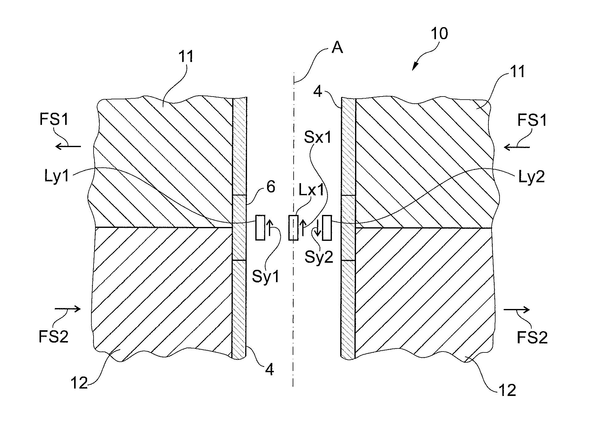
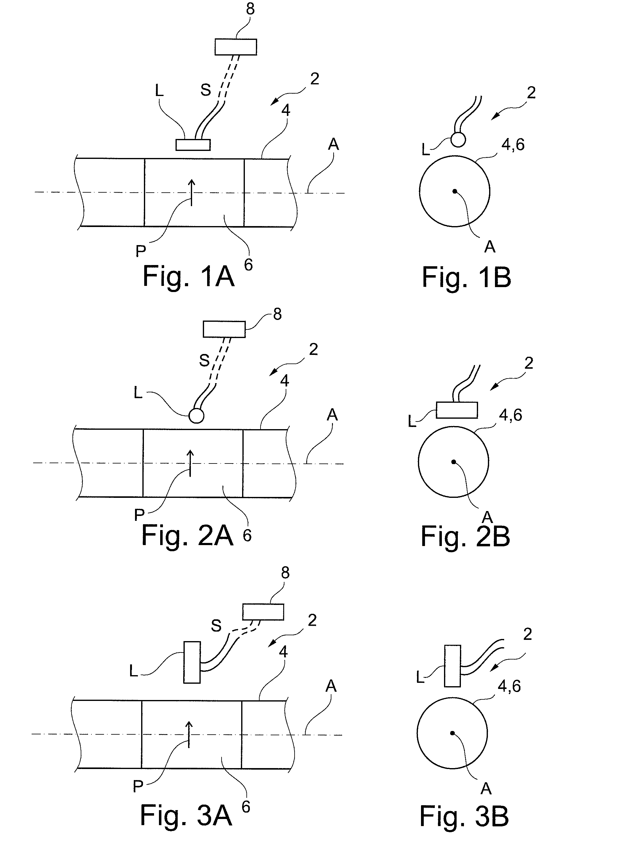
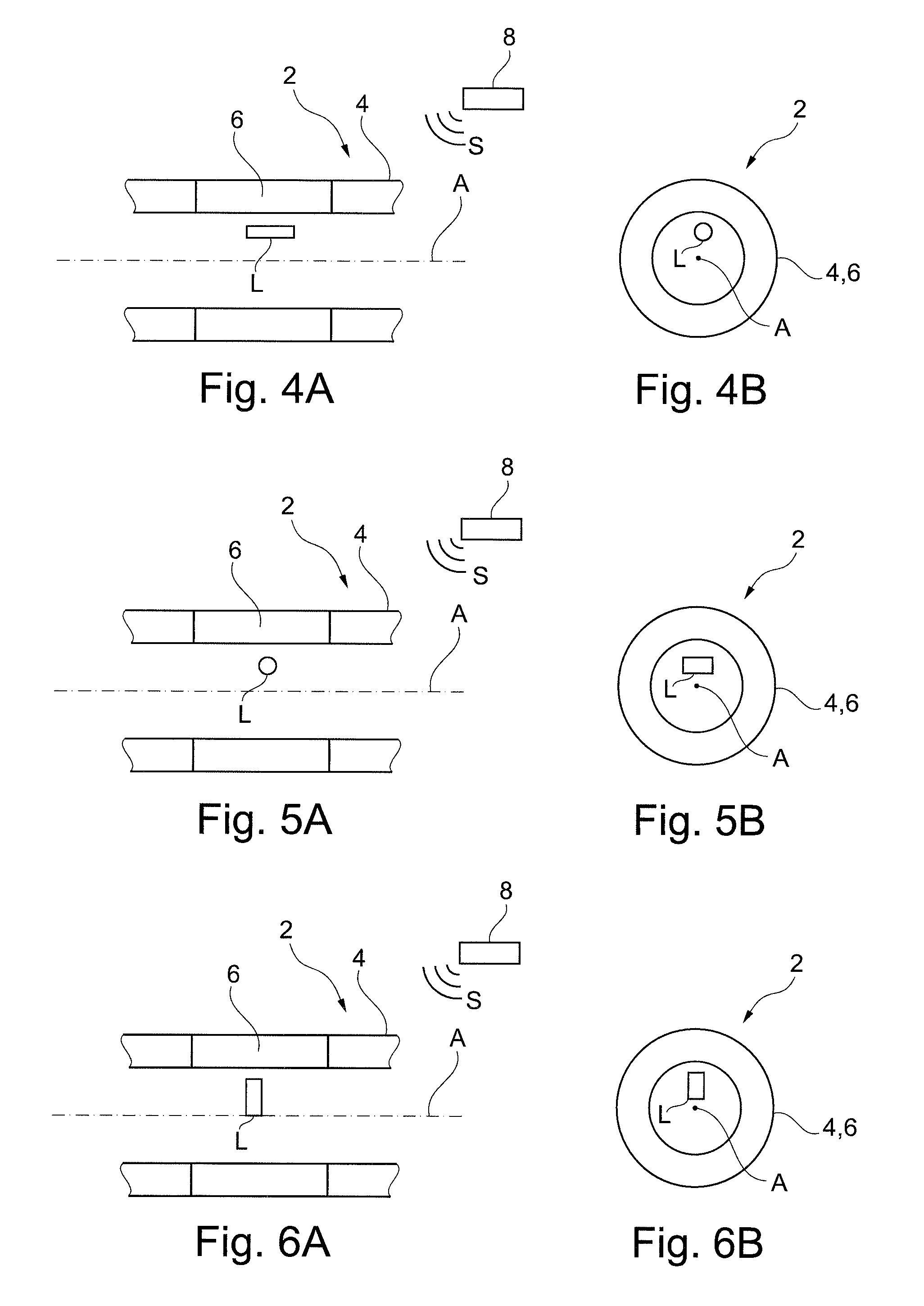
[0051]FIG. 1 A) is a simplified side view of a magneto elastic sensor 2 according to an embodiment of the invention. A rotating shaft like member 4 is provided with a magneto-elastically active region 6 having a circumferential polarization P, the direction of which is indicated by an arrow. When the shaft 4 is subject to a shear stress, which means for example that the shaft portion left from the active region 6 is urged to in a first direction and the shaft portion right from the active region 6 is subject to a counteracting force urging the shaft in opposite direction, the magnetic flux vector emanating from the active region 4 has a component, which is directed in axial direction of the shaft 4. The sensor L detects this component of the shear stress induced magnetic field and outputs a signal S. A processing unit 8 is configured to process this signal S so as to determine the stress, which is applied to the shaft 4. The sensor L has a sensing direction, which is substantially p...


PUM


Abstract

A magneto elastic sensor having a longitudinally extending shaft like member which is subject to a load, is provided. A magneto-elastically active region is directly or indirectly attached to or forming a part of the member in such a manner that the mechanic stress is transmitted to the active region. A magnetically polarized region of the active region becomes increasingly helically shaped as the application stress increases. A magnetic field sensor means is arranged approximate the at least one magneto elastically region for outputting a signal corresponding to a stress induced magnetic flux emanating from the magnetically polarized region. The magnetic sensor means is configured for determination of a shear stress and/or of a tensile or compressive stress. In particular, the sensor means comprises at least one direction sensitive magnetic field sensor, which is arranged having a predetermined and fixed spatial coordination with the member.

Description

FIELD OF THE INVENTION[0001]The invention is related in general to systems and methods involving the use of magnetic field sensors for measuring a load. In particular, the invention is related to a magneto-elastic sensor, a load pin, a ball joint and a tow coupling incorporating this sensor. Furthermore, the invention relates to a method of determining a direction of a load vector.DESCRIPTION OF THE RELATED ART[0002]In the control of systems having a member, which is subject to mechanic forces, the determination of the mechanic load is one of the fundamental parameters of interest. The sensing of the load, the torque, bending, and / or shear stress should be performed in an accurate, reliable and inexpensive manner.[0003]Previously, the measurement of mechanic load was accomplished using contact-type sensors, which are directly attached to the member or are incorporated in said member. A typical contact-type sensor is a strain-gauge. This detector is directly attached to a surface of ...

Claims


Application Information

Patent Timeline
IPC IPC(8): G01L9/00B60D1/24F16C11/06G01N27/72G01P13/02
CPCG01L9/0001G01N27/72B60D1/248F16C11/06G01P13/02G01L1/125Y10T403/20G01L3/102
Inventor GIE IBL, JOHANNES
Owner METHODE ELECTRONICS MALTA
Why Eureka
Try Eureka