

Solid oxide fuel cell column temperature equalization by internal reforming and fuel cascading
a solid oxide fuel cell and column temperature equalization technology, applied in the field of cascaded fuel cell stack system, can solve the problems of consuming more energy for fluid movers in the system (pumps, blowers, compressors), and affecting the efficiency of fuel cells
- Summary
- Abstract
- Description
- Claims
- Application Information
AI Technical Summary
Problems solved by technology
Method used
Image

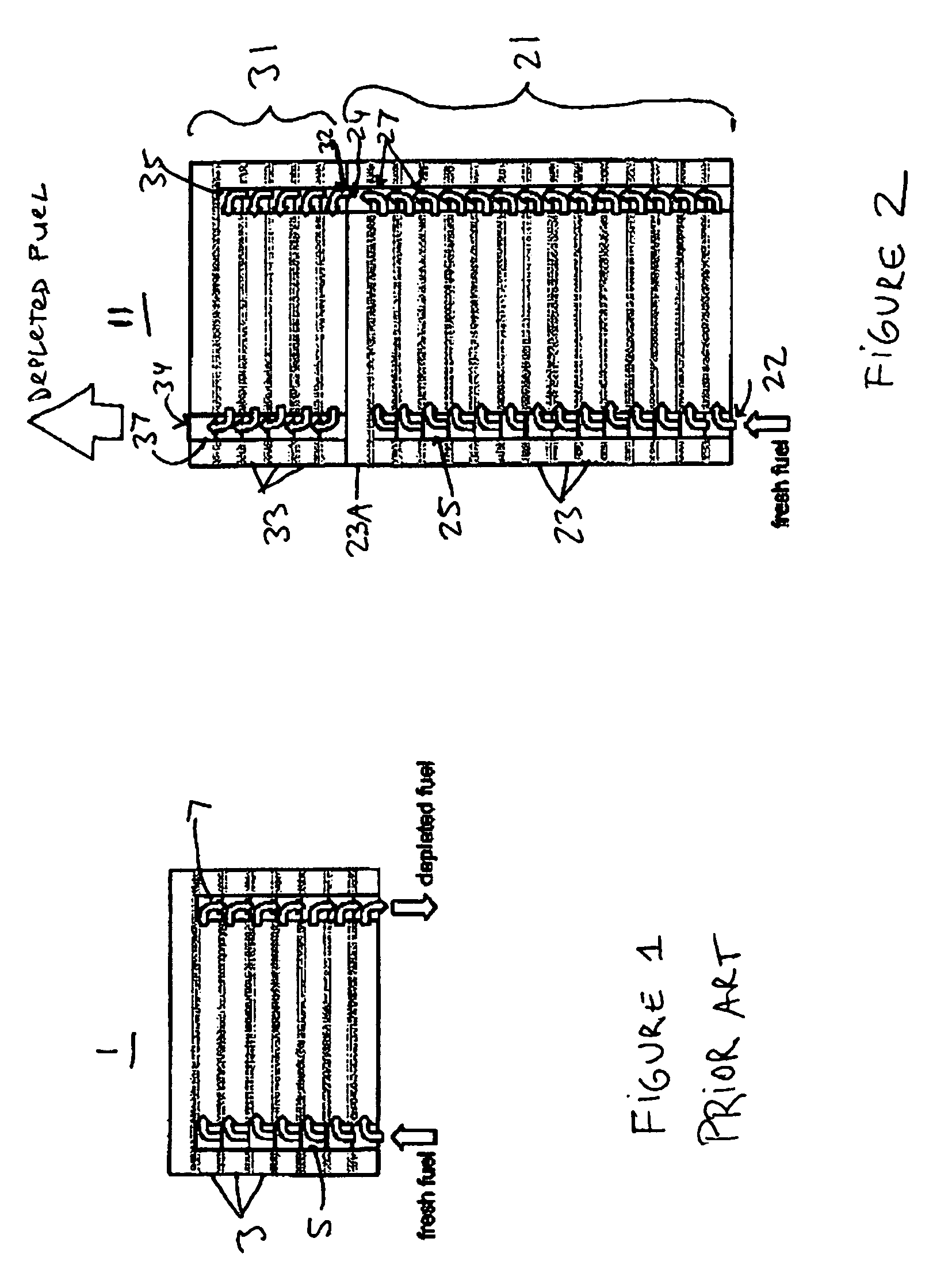
Examples
third embodiment
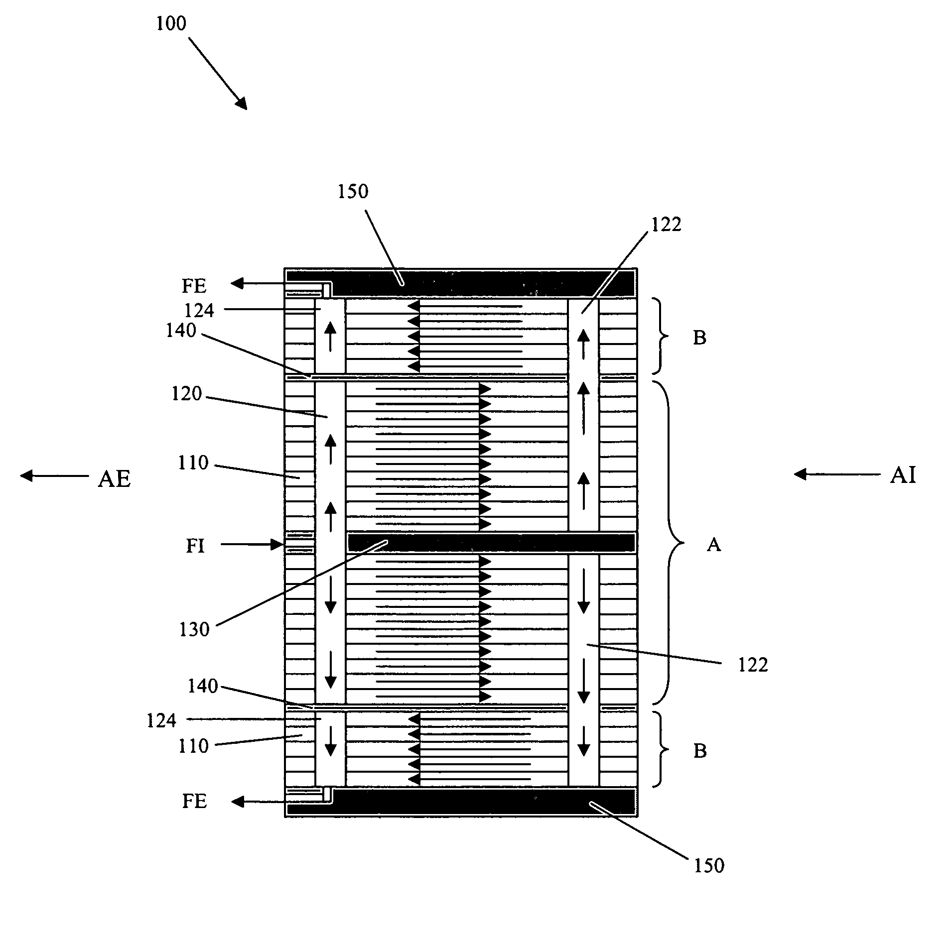
[0036]In the third embodiment, the reformer is selectively thermally integrated with a portion of the first stack 21 which operates at a higher temperature than one or more other portions of the first stack.
[0037]In general, the fuel cells in the middle portion of a fuel cell stack operate at a higher temperature than fuel cells in the end portions of the stack. In vertical fuel cell systems, where the fuel cells are stacked in a vertical direction, this means that the middle fuel cells generally operate at a higher temperature than the upper or lower fuel cells. However, it is possible that in some stack designs, the upper fuel cells may operate at a higher temperature than the lower fuel cells or even the middle fuel cells. Thus, the average operating temperature of the fuel cell system is often kept below a desired temperature in order to maintain the operating temperature of the middle fuel cells below a temperature at which the adjacent metal interconnects are significantly oxi...
second embodiment
[0040]In another aspect of the second embodiment, an external reformer is thermally integrated with the middle portion of the first stack 21. This thermal integration may be provided by placing the reformer in thermal contact with the middle portion of the stack 21 or by providing a thermal conduit or thermally conductive material which connects the middle portion of the stack 21 to the reformer. However, the external reformer is not intentionally thermally integrated with the end portions of the stack (i.e., the reformer is not placed in thermal contact with the end portions of the stack where the upper and lower fuel cells are located). It should be noted that the external reformer may be thermally integrated with an upper portion of the stack 21 if the stack 21 is configured such that the upper portion usually operates at a higher temperature than the middle portion of the stack 21.
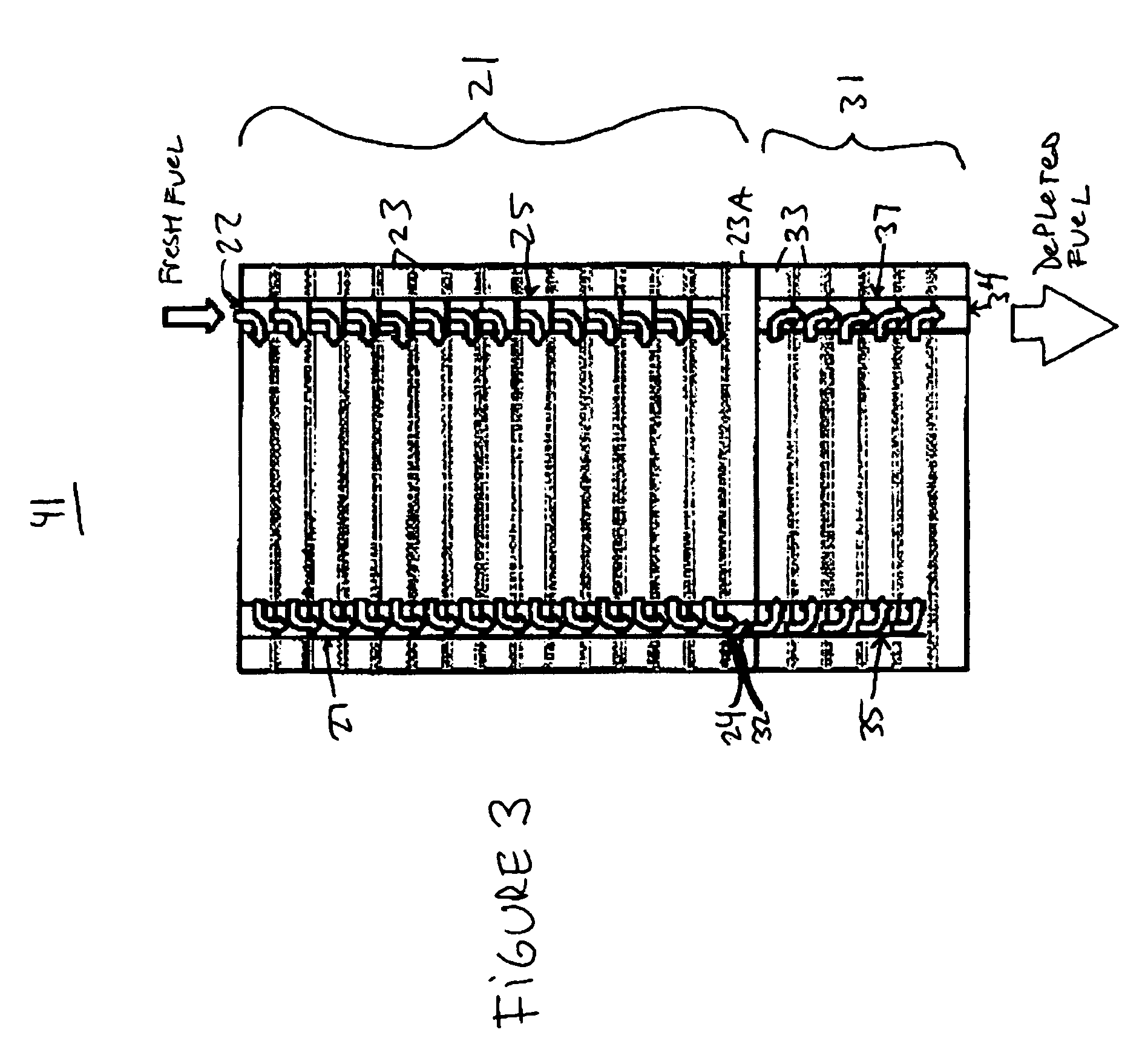
[0041]FIG. 4 schematically illustrates a system 51 in which an external reformer 9 may be thermally...
PUM
| Property | Measurement | Unit |
|---|---|---|
| temperature | aaaaa | aaaaa |
| temperature | aaaaa | aaaaa |
| temperature | aaaaa | aaaaa |
Abstract
Description
Claims
Application Information