Electromechanical relay and method of operating same

a technology of electromechanical relays and relays, applied in the field of relays, can solve the problems of large coil size, high unit-to-unit variability and high unit cost, and the general structure of the assembly-line type process is generally relatively complicated, and can be manufactured by using conventional winding methods. or very difficult,

Inactive Publication Date: 2012-03-27
MAGVENTION (SUZHOU) LTD
View PDF13 Cites 11 Cited by
  • Summary
  • Abstract
  • Description
  • Claims
  • Application Information

AI Technical Summary

Problems solved by technology

The individual relays produced by such an “assembly-line” type process generally have relatively complicated structures and exhibit high unit-to-unit variability and high unit cost.
One drawback of these traditional latching relay designs is that they require the coil to generate a relatively large reversing magnetic field in order to transfer the armature from one position to the other.
This requirement mandates a large number of wire windings for the coil, making the coil size large and impossible or very difficult to fabricate other than using conventional winding methods.
Each of the prior arts, though providing a unique approach to make latching electomechanical relays and possessing some advantages, has some drawbacks and limitations.
These drawbacks and limitations can make manufacturing difficult and costly, and hinder their value in practical applications.

Method used


Image

  • Electromechanical relay and method of operating same
  • Electromechanical relay and method of operating same
  • Electromechanical relay and method of operating same

Examples


example 1

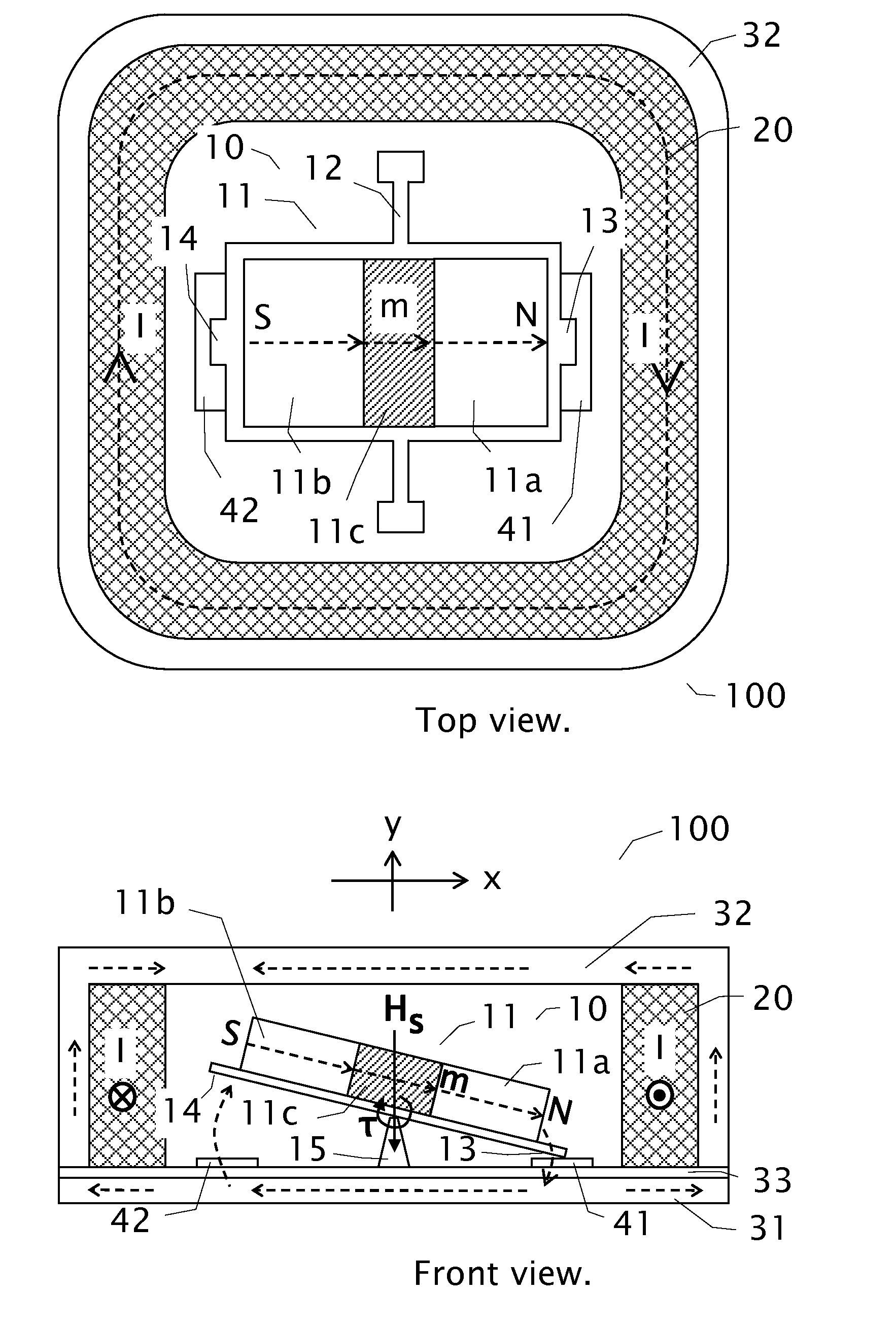
[0030]Assuming the first magnet having the following characteristics:[0031]length=4 mm (along long axis), width=4 mm, thickness=0.2 mm, volume V=length×width×thickness, remnant magnetization Br=μ0M=1 T, the magnetic moment μ0m=μ0M×V=3.2×10⁻⁹ T·m3. For a coil-induced magnetic field μ0Hs=0.05 T (Hs=500 Oe), the induced magnetic torque about the length center is τ=μ0m×Hs=1.27×10⁻⁴ m·N (assuming m is perpendicular to Hs) which corresponds to a force of Fm=τ / (length / 2)=6.4×10⁻² N at the end of the first magnet. The above exemplary parameters show that for a relatively small coil-induced magnetic field (Hs=500 Oe), a significantly large torque and force can be generated. The torque and force can continue to increase with larger Hs (correspondingly larger coil current). Another point worth noting is that when the angle between m and Hs changes from perfectly perpendicular (90°) to 80°, the change in the magnitude of the torque (and force) is only 1.5%=1−98.5%=1−sin(80°), which gives a larg...


PUM


Abstract

An electromechanical relay employing a movable first magnet and a nearby switching electromagnet is disclosed. The movable first magnet is permanently magnetized with a magnetic moment and has at least a first end. The switching electromagnet, when energized, produces a switching magnetic field which is primarily perpendicular to the magnetization direction of the first movable magnet and exerts a magnetic torque on the first magnet to force the first magnet to rotate and closes an electrical conduction path at the first end. Changing the direction of the electrical current in the switching electromagnet changes the direction of the switching magnetic field and thus the direction of the magnetic torque on the first magnet, and causes the first magnet to rotate in an opposite direction and opens the electrical conduction path at the first end. Multiple magnetic layers can be arranged to form closed magnetic circuits to facilitate switching and maintaining switched states. Latching and non-latching types of relays can be formed by appropriately adjusting various force magnitudes.

Description

CROSS-REFERENCE TO RELATED APPLICATIONS[0001]This patent application claims the benefit of U.S. Provisional Patent Application Ser. No. 61 / 154,435, filed on Feb. 23, 2009, which is hereby incorporated by reference. This application is related to application Ser. No. 11 / 534,655, filed on Sep. 24, 2006, now U.S. Pat. No. 7,482,899 B2, issued on Jan. 27, 2009.FIELD OF THE INVENTION[0002]The present invention relates to relays. More specifically, the present invention relates to electromechanical relays and to methods of operating and formulating electromechanical relays.BACKGROUND OF THE INVENTION[0003]Relays are electromechanical switches operated by a flow of electricity in one circuit controlling the flow of electricity in another circuit. A typical relay consists basically of an electromagnet with a soft iron bar, called an armature, held close to it. A movable contact is connected to the armature in such a way that the contact is held in its normal position by a spring. When the e...

Claims


Application Information

Patent Timeline
Patent Type & Authority Patents(United States)
IPC IPC(8): H01H51/22
CPCH01H50/005H01H2001/0042H01H2036/0093H01H2050/007
Inventor SHEN, JUN
Owner MAGVENTION (SUZHOU) LTD
Why Eureka
Try Eureka