Method of placing a substrate, method of transferring a substrate, support system and lithographic projection apparatus

a technology of lithographic projection apparatus and substrate, which is applied in the direction of optical devices, instruments, photomechanical devices, etc., can solve the problems of poor accuracy and introduction of overlay errors

Active Publication Date: 2012-04-03
ASML NETHERLANDS BV
View PDF19 Cites 8 Cited by
  • Summary
  • Abstract
  • Description
  • Claims
  • Application Information

AI Technical Summary

Benefits of technology

[0015]In another embodiment, there is provided a support system for supporting a substrate, the support system including a substrate holder configured to hold the substrate, the substrate holder comprising a surface provided with a plurality of burls, a substrate handling device configured to place a substrate on the substrate holder in accordance with substrate placement data, a measurement unit configured to perform measurement useable for determining a position of the plurality of burls provided on the surface of the substrate holder, a processor configured to determine substrate placement data, the substrate placement data enabling placement of the substrate on the surface of the substrate holder at a certain position with respect to the position of the plurality of burls.

Problems solved by technology

Poor accuracy results in overlay.
Consequently, an overlay error has been introduced.

Method used


Image

  • Method of placing a substrate, method of transferring a substrate, support system and lithographic projection apparatus
  • Method of placing a substrate, method of transferring a substrate, support system and lithographic projection apparatus
  • Method of placing a substrate, method of transferring a substrate, support system and lithographic projection apparatus

Examples


first embodiment

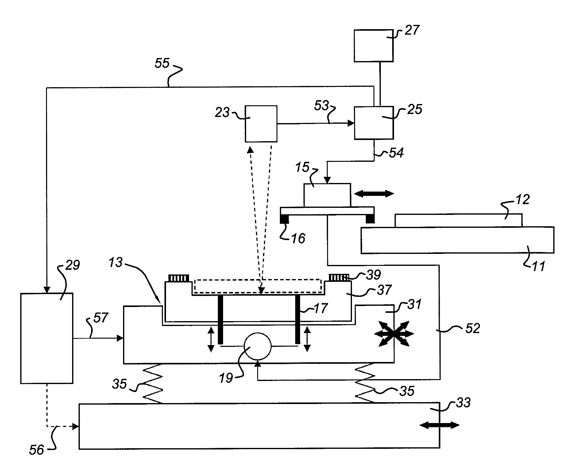
[0079]FIG. 4 schematically depicts a flow chart of a method of placing a substrate onto a surface of a substrate holder according to the invention. First, in action 61, an image of a plurality of burls on a surface of a substrate holder is acquired by means of an imaging apparatus. In case a transfer system as schematically depicted in FIG. 3 is used, the plurality of burls are provided on the second substrate holder 13 and the imaging apparatus corresponds to measurement unit 23.

[0080]Subsequently, in action 63, the position of the plurality of burls on the surface of the substrate holder is determined by processing of the image. This processing is performed by a processor. In case a transfer system as schematically depicted in FIG. 3 is used, the processor corresponds to processor 25. In an embodiment, the processing of the image involves the use of a pattern recognition technique.

[0081]Then, in action 65, the substrate placement data for enabling placement of the substrate at an ...

second embodiment

[0083]FIG. 5 schematically depicts a flow chart of a method of placing a substrate onto a surface of a substrate holder according to the invention. In this embodiment, in action 71, first, the position of each burl of a plurality of burls provided on a surface of a substrate holder is measured by means of a measurement sensor. In case a transfer system is used as schematically shown in FIG. 3, the measurement sensor corresponds with measurement unit 23 and the substrate holder corresponds with the second substrate holder 13.

[0084]Subsequently, in action 73, the position of the plurality of burls on the surface of the substrate holder by processing the position of each burl as measured. The construction by processing is performed by a processor. In case a transfer system is used as schematically depicted in FIG. 3, the processor corresponds with processor 25.

[0085]Then, in action 75, again substrate placement data are calculated for enabling placement of the substrate at an optimal p...

third embodiment

[0087]FIG. 6 schematically depicts a flow chart of a method of placing a substrate onto a surface of a substrate holder according to the invention. First, in action 81, a memory is provided. The memory comprises position data related to a position of a plurality of burls on a surface of a substrate holder. In case a transfer system is used as schematically depicted in FIG. 3, the memory corresponds to memory 27.

[0088]Additionally, in action 83, a substrate is provided. The substrate comprises a plurality of marks.

[0089]Subsequently, in action 85, the substrate is placed at a first position on the surface of the substrate holder, the position of each mark of the plurality of marks is measured, and a quality indicator is calculated. The quality indicator is a numerical value representing the quality of a certain position, i.e., a measure for an overlay error or a measure for the average amount of deformation taking place at that certain position.

[0090]In FIG. 7a, a top view of a subst...


PUM


Abstract

A method is provided for placing a substrate onto a surface of a substrate holder, the surface having a plurality of burls. First substrate placement data is calculated. This data enables placement of the substrate at a certain position with respect to a position of the plurality of burls on the surface of the substrate holder. Then, the substrate is placed at the certain position in accordance with the substrate placement data. The certain position may be based on the position at which placement would result in a minimized overlay error or may be based on the position at which placement would result in minimized substrate deformation.

Description

CROSS-REFERENCE TO RELATED APPLICATION[0001]This application claims the benefit of the filing date of U.S. Provisional Application 60 / 960,699 filed on Oct. 10, 2007. The subject matter of that application is incorporated herein by reference as if fully set forth herein.BACKGROUND OF THE INVENTION[0002]1. Field of Invention[0003]The inventions relate in general to placing a substrate onto a surface of a substrate holder. They further relate to transferring a substrate from a first substrate holder to a second substrate holder using a transfer unit. The inventions further relate to a support system for supporting a substrate, a lithographic apparatus comprising such a support system and device manufacturing using such a lithographic apparatus.[0004]2. Related Art[0005]A lithographic apparatus applies a desired pattern onto a substrate, usually onto a target portion of the substrate. A lithographic apparatus can be used, for example, in the manufacture of integrated circuits (ICs). In ...

Claims


Application Information

Patent Timeline
Patent Type & Authority Patents(United States)
IPC IPC(8): G03B27/58G03B27/62
CPCG03F7/70633G03F7/70783
Inventor ALBERTI, JOZEF AUGUSTINUS MARIAVAN NUNEN, GERARDUS PETRUS MATTHIJSGROENSMIT, FRANS ERIKCOMPEN, RENE THEODORUS PETRUSSOETHOUDT, ABRAHAM ALEXANDER
Owner ASML NETHERLANDS BV
Why Eureka
Try Eureka