Iron-type golf club

a golf club and iron-type technology, applied in golf clubs, golf, sport apparatus, etc., can solve the problems of no support for the hitting face and thinner striking face, and achieve the effect of improving the center of gravity disposition of the club head, increasing the moment of inertia and the size of the sweet spo

Active Publication Date: 2012-04-17
ACUSHNET CO
View PDF100 Cites 84 Cited by
  • Summary
  • Abstract
  • Description
  • Claims
  • Application Information

AI Technical Summary

Benefits of technology

[0008]The present invention is directed to iron-type golf club. The inventive iron-type golf club provides a club head that provides the aesthetics of a muscle back iron while improving club head center of gravity disposition, increasing moment of inertia and sweet spot size.

Problems solved by technology

The striking face is thinner for long irons, but no support is provided to the hitting face.

Method used


Image

  • Iron-type golf club
  • Iron-type golf club
  • Iron-type golf club

Examples


Embodiment Construction

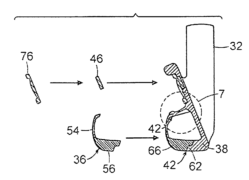
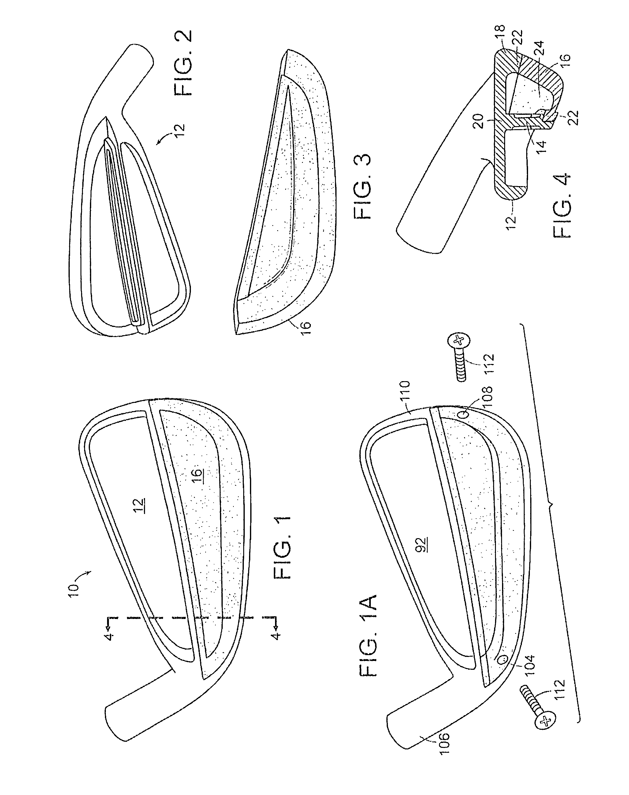
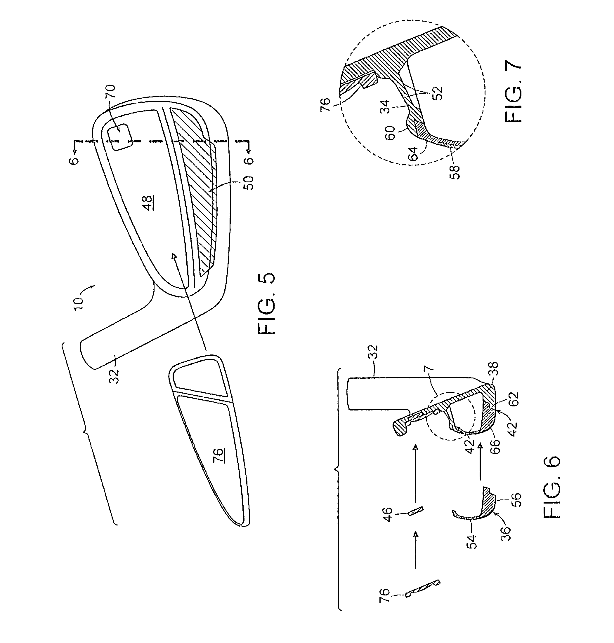
[0054]The present invention is directed to hollow iron-type golf clubs and can also be used with utility golf clubs. The inventive iron-type golf club provides the aesthetics of a muscle back iron while moving the center of gravity lower and further back, increasing moment of inertia, and enlarging sweet spot similar to a cavity back club. The inventive club can accomplish this goal by incorporating a hollow interior cavity in the muscle portion of the club, supporting a thin hitting face with a supporting member, and adding a high density rear sole portion. Additionally, weight from the upper toe can be redistributed to other portions of the club head to improve mass characteristics, and can be advantageously replaced by a vibration and sound dampener. The end result of the present invention is a club that resembles a muscle back iron that low handicap players use, but the club plays like the forgiving cavity back irons that high handicap players prefer. Several embodiments of the ...


PUM


Abstract

A golf club including a club head having a club head main body including a hitting face and a face support, and a support extension. The support extension extends between the face support and a back flange to define a lower cavity.

Description

CROSS-REFERENCE TO RELATED APPLICATIONS[0001]This application is a continuation-in-part of U.S. patent application Ser. No. 12 / 099,244 filed Apr. 8, 2008, which is a continuation-in-part of U.S. patent application Ser. No. 11 / 854,689, filed Sep. 13, 2007, the contents of which are incorporated herein by reference in their entirety.FIELD OF THE INVENTION[0002]This invention generally relates to golf clubs, and more specifically to iron-type golf club having an enclosed lower hollow cavity behind the hitting face.BACKGROUND OF THE INVENTION[0003]Typical iron club heads are solid with a flat hitting face and generally either muscle back and cavity back clubs. Traditionally all irons were muscle back, which are smooth at the back with low offset, thin topline and thin sole. Cavity back irons have a hollowed out back and the club head mass is redistributed to the sole and the perimeter of the club head, which moves the center of gravity lower to the ground and rearward making the iron la...

Claims


Application Information

Patent Timeline
Patent Type & Authority Patents(United States)
IPC IPC(8): A63B53/04
CPCA63B53/047A63B53/0475A63B59/0092A63B2053/0454A63B2209/00A63B2209/10A63B2053/0416A63B60/54A63B53/0454A63B53/0416
Inventor GILBERT, PETER J.JORGENSEN, DOUGLAS C.KNUTSON, SCOTT A.RICK, HELENESTANESCU, ADRIAN L.
Owner ACUSHNET CO
Why Eureka
Try Eureka