
Wireless communication apparatus, program, wireless communication method and wireless communication system

wireless communication technology, applied in the field of wireless communication apparatus, a program, a wireless communication method and a wireless communication system, can solve the problems of reducing needless communication, and apparatus at the receiving end that fails to receive it normally, so as to improve the efficiency of wireless communication

Active Publication Date: 2012-04-17
SONY CORP
View PDF14 Cites 7 Cited by
  • Summary
  • Abstract
  • Description
  • Claims
  • Application Information

AI Technical Summary

Benefits of technology

[0013]In light of the foregoing, there is a need for new, improved wireless communication apparatus, program, wireless communication method and wireless communication system which perform dynamic processing when a reception confirmation signal is not normally received and thereby improve the efficiency of wireless communication.
[0028]According to the embodiments of the present invention described above, it is possible to perform dynamic processing when a reception confirmation signal is not normally received and thereby improve the efficiency of wireless communication.

Problems solved by technology

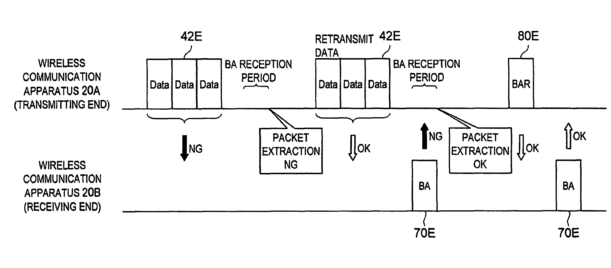
However, when the apparatus at the receiving end normally receives an A-MPDU packet but the apparatus at the transmitting end fails to receive BA, the retransmission of the A-MPDU packet as in the above processing (1) causes needless communication.
Further, in view of a data buffer in the apparatus at the receiving end, even if the apparatus at the transmitting end transmits a new A-MPDU packet as in the above processing (3), it is likely that the apparatus at the receiving end fails to receive it normally.
Thus, if one of the above processing (1) to (3) is always performed when the apparatus at the transmitting end fails to receive BA, needless data is transmitted and received, which causes a decrease in the efficiency of wireless communication.

Method used


Image

  • Wireless communication apparatus, program, wireless communication method and wireless communication system
  • Wireless communication apparatus, program, wireless communication method and wireless communication system
  • Wireless communication apparatus, program, wireless communication method and wireless communication system

Examples


Embodiment Construction

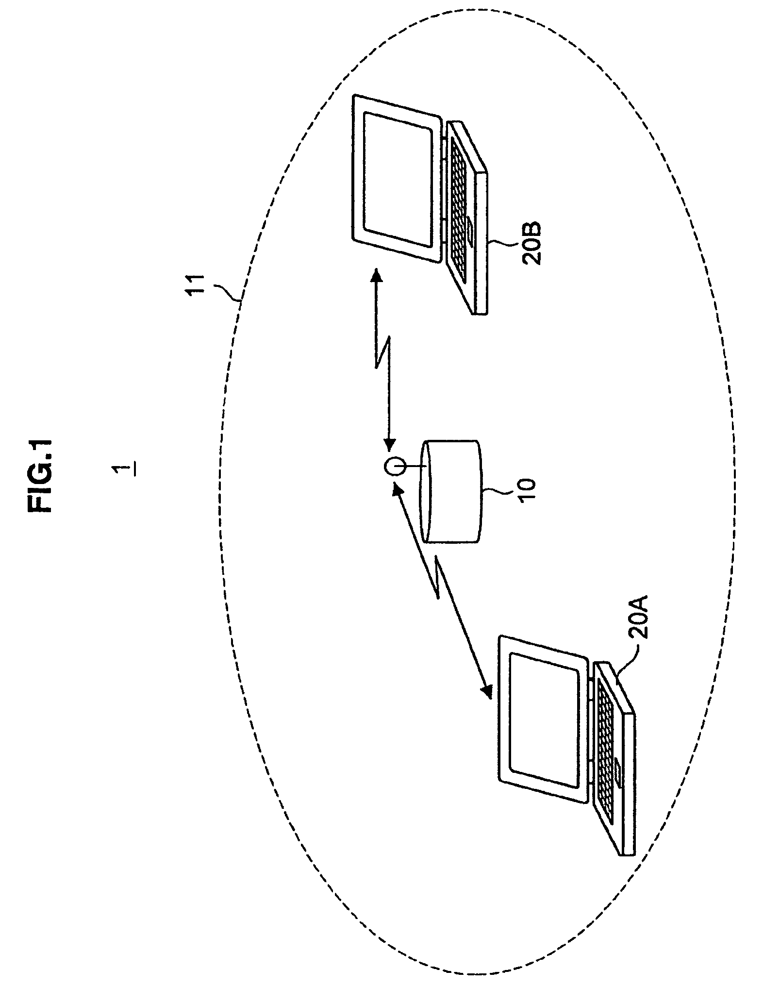
[0046]Hereinafter, preferred embodiments of the present invention will be described in detail with reference to the appended drawings. Note that, in this specification and the appended drawings, structural elements that have substantially the same function and structure are denoted with the same reference numerals, and repeated explanation of these structural elements is omitted.

[0047]Preferred embodiments of the present invention will be described in the following order:

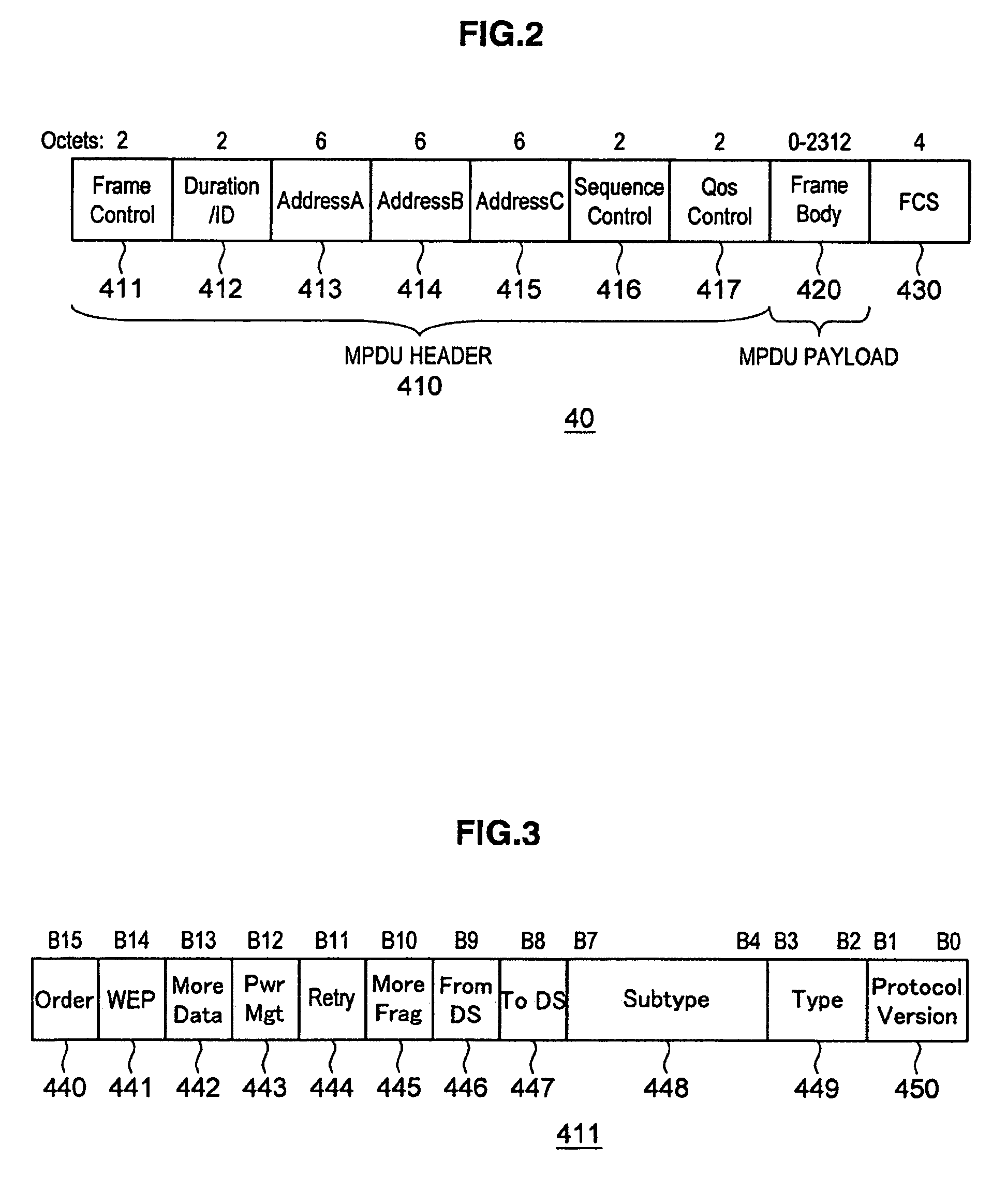
[0048](1) Outline of the wireless communication system according to an embodiment of the present invention[0049](1-1) Configuration of the wireless communication system[0050](1-2) Exemplary format of data communicated over the wireless communication system[0051](1-3) Objective of the wireless communication system according to the embodiment of the present invention

[0052](2) Configuration of the wireless communication apparatus which constitutes the wireless communication system[0053](2-1) Hardware configuration of t...


PUM


Abstract

A wireless communication apparatus includes a transmitting portion to transmit a data signal to other wireless communication apparatus, a receiving portion to receive a reception confirmation signal indicating reception of the data signal by the other wireless communication apparatus from the other wireless communication apparatus during a specified period, a determination portion to determine that a predetermined requirement is satisfied if the receiving portion receives a given signal during the specified period, and a control portion to control the transmitting portion to request the other wireless communication apparatus to retransmit the reception confirmation signal if the receiving portion does not normally receive the reception confirmation signal and the determination portion determines that the predetermined requirement is satisfied.

Description

CROSS REFERENCES TO RELATED APPLICATIONS[0001]The present invention contains subject matter related to Japanese Patent Application JP 2007-129654 filed in the Japan Patent Office on May 15, 2007, the entire contents of which being incorporated herein by reference.BACKGROUND OF THE INVENTION[0002]1. Field of the Invention[0003]The present invention relates to a wireless communication apparatus, a program, a wireless communication method and a wireless communication system.[0004]2. Description of the Related Art[0005]A wireless communication system based on the IEEE (Institute of Electrical and Electronic Engineers) 802.11 standards has been widespread. A wireless communication apparatus which constitutes such a wireless communication system is more advantageous than a wired communication system in that it has a high degree of flexibility such as portability. Further, an application which is used in each wireless communication apparatus becomes various, and a transmission speed which ...

Claims


Application Information

Patent Timeline
Patent Type & Authority Patents(United States)
IPC IPC(8): G06F11/00H04J1/16H04J3/14H04L1/00H04W28/04H04W88/06
CPCH04L1/0073H04L1/1614H04W88/06H04L1/0057H04L1/188
Inventor YOSHIMURA, OSAMU
Owner SONY CORP
Learn More