System and method for managing a flow based reply cache

a reply cache and flow-based technology, applied in the field of storage systems, can solve problems such as data corruption, system return failure, active clients “starving” slower/retransmitting clients,

Active Publication Date: 2012-05-01
NETWORK APPLIANCE INC
View PDF65 Cites 31 Cited by
  • Summary
  • Abstract
  • Description
  • Claims
  • Application Information

AI Technical Summary

Benefits of technology

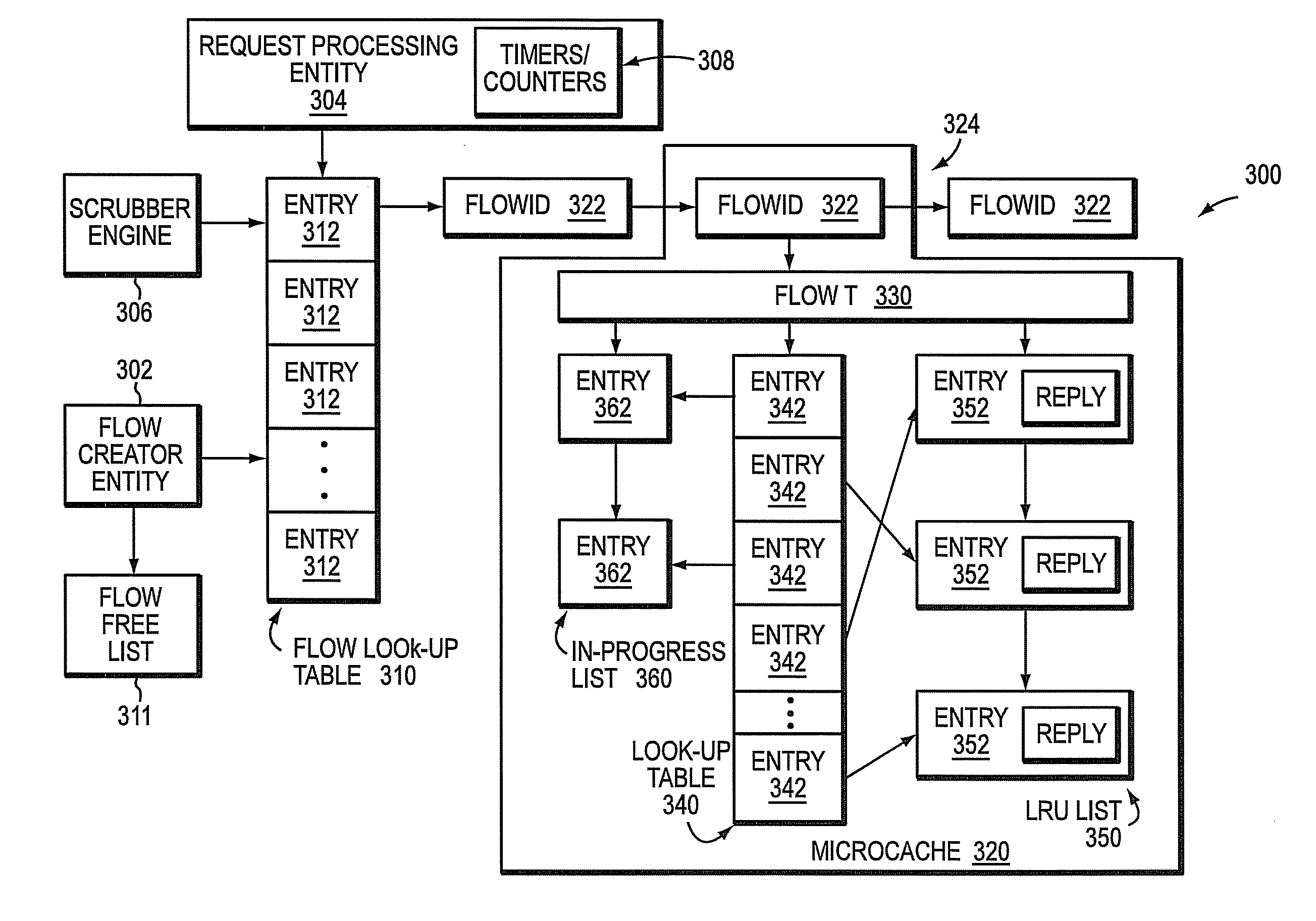
[0012]Briefly, the present invention relates to managing a flow based reply cache. The flow based reply cache may be organized into one or more microcaches each having a plurality of entries. Each microcache may be allocated to a client of the storage system, such that each client has a set of entries that is not shared with other clients. The flow based reply cache may be managed through the operation of a flow creator entity, a request processing entity and a scrubber engine. The flow creator entity may organize the flow based reply cache into microcaches. The request processing entity may process requests issued by the clients of the storage system. The scrubber engine may be configured to expire the entries of a microcache allocated to a client based on one more predefined criteria.

Problems solved by technology

The file system then attempts to process the rename request again but, since file A has already been renamed to file B, the system returns a failure, e.g., an error reply, to the client (even though the operation renaming file A to file B had been successfully completed).
A reply cache attempts to prevent such failures by recording the fact that the particular request was successfully executed, so that if it were to be reissued for any reason, the same reply will be resent to the client (instead of re-executing the previously executed request, which could result in an inappropriate error reply).
Such long retransmit times often result in active clients “starving” slower / retransmitting clients of entries in the reply cache, such that it is unlikely that a retransmitted duplicate non-idempotent request (in a deployment using NFS over TCP) will be found in a global LRU reply cache.
The ensuing cache miss results in a replay of the non-idempotent operation and, potentially, data corruption.

Method used


Image

  • System and method for managing a flow based reply cache
  • System and method for managing a flow based reply cache
  • System and method for managing a flow based reply cache

Examples


Embodiment Construction

Overview

[0020]The present invention is directed to managing a flow based reply cache. Instead of using a global least recently used (LRU) implementation, cache entries are stored on a per-client connection basis. As used herein, the term “client connection” denotes either a TCP connection, UDP packets grouped into the same logical network data flow, or any other identifier, derived from underlying protocols, used to differentiate data sent from a client. A protocol server, which in an embodiment may be a Network File System (NFS) server although other protocol servers may be used, executing on a storage system maintains a microcache for each client connection or logical data flow to store and retrieve recent replies for requests, e.g., NFS requests, issued by a client. Each microcache may be dynamically managed and tuned for each data flow. By maintaining a microcache for each client connection in a non-global manner, the NFS server can prevent an aggressive client, e.g., a client i...


PUM


Abstract

A system and method determines when the entries of a reply cache, organized into microcaches each of which is allocated to a client connection, may be retired or released, thereby freeing up memory structures. A plurality of connection statistics are defined and tracked for each microcache and for the entries of the microcache. The connection statistics indicate the value of the microcache and its entries to the client. The connection statistics include a measure of the time since the last idempotent or non-idempotent request (TOLR) was received, and a count of the number of idempotent requests that have been received since the last non-idempotent request (RISLR). A microcache with a TOLR time and a RISLR count that exceed respective thresholds may be expired and removed from the reply cache.

Description

CROSS-REFERENCE TO RELATED APPLICATIONS[0001]The present application is related to commonly assigned U.S. patent application Ser. No. 12 / 105,914, which was filed on Apr. 18, 2008, by Jason L. Goldschmidt, Peter D. Shah, and Thomas M. Talpey for a FLOW BASED REPLY CACHE, and is hereby incorporated by reference in its entirety.BACKGROUND OF THE INVENTION[0002]1. Field of the Invention[0003]The present invention relates to storage systems and, more specifically, to managing a reply cache used in a storage system.[0004]2. Background Information[0005]A storage system is a computer that provides storage services relating to the organization of information on writeable persistent storage devices, such as non-volatile memories and / or disks. The storage system typically includes a storage operating system that implements a file system to logically organize the information as a hierarchical structure of data containers, such as files and directories on, e.g., the disks. Each “on-disk” file ma...

Claims


Application Information

Patent Timeline
Patent Type & AuthorityPatents(United States)
IPC IPC(8): G06F13/00
CPCH04L67/2852H04L67/5682
InventorGOLDSCHMIDT, JASON L.SHAH, PETER D.TALPEY, THOMAS M.
OwnerNETWORK APPLIANCE INC