Modular rack assembly

a module and rack technology, applied in the field of modules, can solve the problems of difficult assembly and adjustment, high manufacturing cost, and inability to easily configure for shipping

Inactive Publication Date: 2012-05-08
SILVERACK
View PDF32 Cites 30 Cited by
  • Summary
  • Abstract
  • Description
  • Claims
  • Application Information

AI Technical Summary

Problems solved by technology

While there are a variety of modular rack assemblies that have been designed to store various items, they are not easily configurable for shipping.
Further, conventional modular racks are not formed of a simple construction and may be expensive to manufacture and difficult to assemble and adjust.

Method used


Image

  • Modular rack assembly
  • Modular rack assembly
  • Modular rack assembly

Examples


Embodiment Construction

[0033]In the following detailed description, only certain exemplary embodiments of the present invention have been shown and described, simply by way of illustration. As those skilled in the art would realize, the described embodiments may be modified in various different ways, all without departing from the spirit or scope of the present invention. Accordingly, the drawings and description are to be regarded as illustrative in nature and not restrictive. Like reference numerals designate like elements throughout the specification.

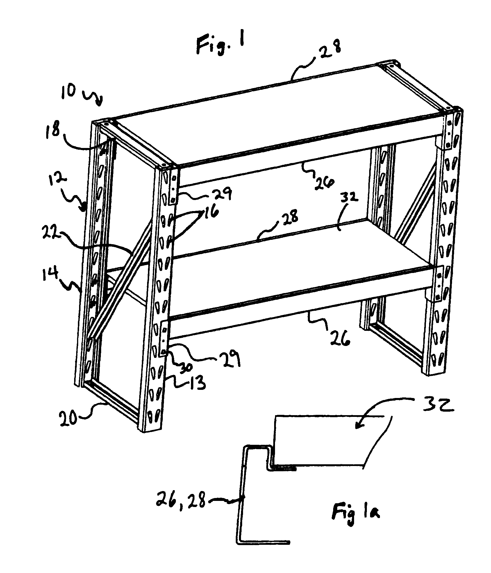
[0034]With reference to FIG. 1 there is shown a boltless storage rack assembly 10 according to an embodiment of the present invention. The rack assembly 10 comprises right and left end support units 12, each end support unit 12 comprising a front support post 13, a rear support post 14, an upper brace 18, a lower brace 20, and a diagonal brace 22. The upper, lower and diagonal braces 18, 20, 22 are fixedly attached at their ends, preferably by welding, to ...


PUM


Abstract

An end support unit for supporting the ends of at least one front and one rear cross beam including: a front support post having a column of slots along its length for receiving at least one slot engaging member of the front cross beam; a rear support post having a column of slots along its length for receiving at least one slot engaging member of the rear cross beam; an upper brace fixedly extending from the upper end of the front support post to the upper end of the rear support post; a lower brace fixedly extending from the lower end of the front support post to the lower end of the rear support post; and a diagonal brace extending diagonally between the front support post and the rear support post.

Description

CROSS-REFERENCE TO RELATED PATENT APPLICATION[0001]This application claims priority to and the benefit of U.S. Patent Application Ser. No. 61 / 050,992, filed on May 6, 2008, in the United States Patent and Trademark Office, the entire content of which is incorporated herein by reference.BACKGROUND OF THE INVENTION[0002]The present invention relates to a modular rack assembly. While there are a variety of modular rack assemblies that have been designed to store various items, they are not easily configurable for shipping. Further, conventional modular racks are not formed of a simple construction and may be expensive to manufacture and difficult to assemble and adjust.SUMMARY OF THE INVENTION[0003]An embodiment of the present invention provides an end support unit for supporting the ends of at least one front and one rear cross beam including: a generally vertical front support post having at least one column of slots along its length for receiving at least one slot engaging member of...

Claims


Application Information

Patent Timeline
Patent Type & Authority Patents(United States)
IPC IPC(8): A47B45/00
CPCA47B47/021A47B57/22A47B87/0207B25H1/02B25H1/12A47B47/027
Inventor EUSTACE, BRIANDAVID, DAN
Owner SILVERACK
Why Eureka
Try Eureka