Locking device for a movable member in a chair

a technology for locking devices and movable parts, which is applied in the direction of chairs, movable seats, couplings, etc., can solve the problems of poor operation, time-consuming, complicated, etc., and achieve the effect of reducing the number of parts and mounting easily and securely

Inactive Publication Date: 2012-05-08
OKAMURA CORP
View PDF21 Cites 1 Cited by
  • Summary
  • Abstract
  • Description
  • Claims
  • Application Information

AI Technical Summary

Benefits of technology

[0009]It is an object of the invention to provide a locking device for a movable member in a chair, in which an operating lever is mounted to a support member without use of screws and is mounted easily and securely with the reduced number of parts.

Problems solved by technology

To move the operating rod, it is necessary for the occupant to leave the seat or to stand up thereby causing poor operativity.
In JP2005-163966A, in order to mount the operating lever, it is necessary to fix the holding metal tool to the support member, which is complicated and needs time.

Method used


Image

  • Locking device for a movable member in a chair
  • Locking device for a movable member in a chair
  • Locking device for a movable member in a chair

Examples


first embodiment

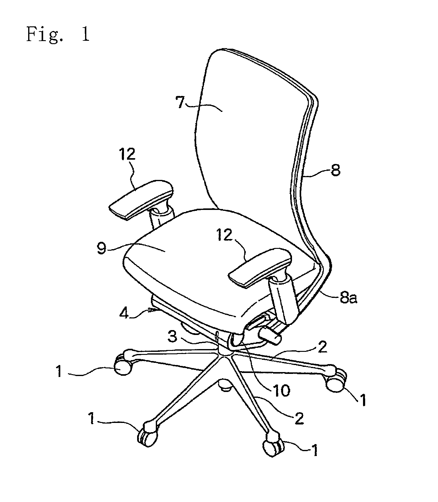
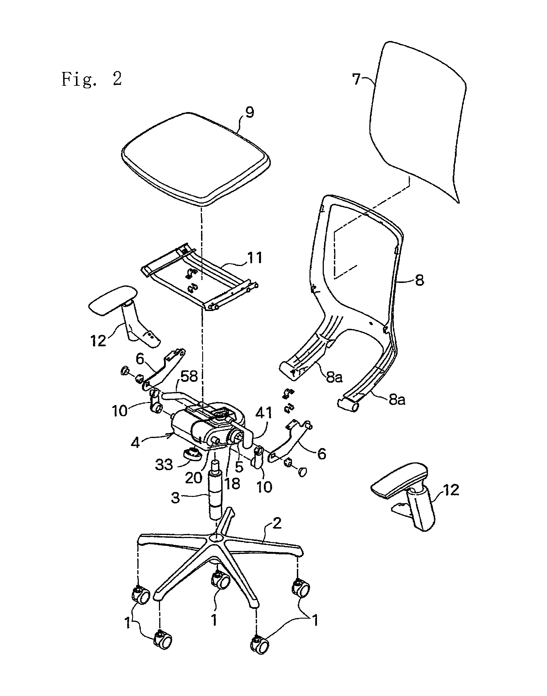
[0025]FIG. 1 is a front perspective view of a chair comprising a locking device according to the present invention, and FIG. 2 is an exploded perspective view thereof.

[0026]The chair comprises a telescopic column 3 at the center of five radial legs 2 each of which has a caster 1 at the end; a support base 4 at the upper end of the column 3; a pivot shaft 5 which passes through the support base 4; a pair of brackets 6,6 each fixed to each end of the pivot shaft 5; a backrest frame 8 which supports the backrest 7 and connects the pivot shaft 5 and the brackets 6 to a pair of front rod portions 8a,8a extending from the lower end of the backrest frame 8 to turn together around the support base 4; a seat frame 11 coupled to the front part of the support base 4 with a pair of link levers 10,10 to move rearward and downward of the support base 4 with rearward tilting of the backrest frame 8; and armrests 12,12 at each side of a seat 9.

[0027]FIGS. 3-5 are exploded perspective views showing ...

second embodiment

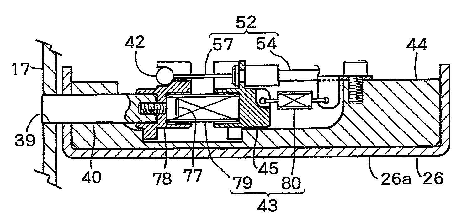
[0096]FIG. 15 shows a locking device according to the present invention. The same numerals are allotted to the same members, and detailed description thereof is omitted.

[0097]To a slider 45 which is attached to a case 44 to slide in the same direction as that of the lock pin 40, the end of an outer tube 54 of a Bowden cable 52 is mounted. A wire end 42 is mounted to the end of a retractable wire 57 which extends leftward from the end of the outer tube 54. The wire end 42 is mounted to a bracket 78 fixed to the right end of the lock pin 40 with a screw 77. There is a shorter distance between the end of the outer tube 54 and the wire end 42 in FIGS. 15A and 15D which is called an pre-unlocking condition; and a longer distance therebetween in FIGS. 15B and 15C which is called a pre-locking condition.

[0098]The first urging unit in an urging unit 43 is a compression spring 79 between a bracket 78 and the slider 45, and the second urging unit in the urging unit 43 is a coil spring 80 moun...


PUM


Abstract

An easily operable lock device for a movable member of a chair, the lock device being adapted such that a person sitting on the chair can select lock or unlock position by operating operation means with a load, such as the weight of the person, acting on the movable member and, when the load is removed after the selection of the lock or unlock position, lock or unlock operation is executed. A lock pin provided at a spring receiving member functioning as a movable member, is selectively engaged with and disengaged from engagement holes formed in a reinforcement plate functioning as a support member. The lock device has biasing means for biasing the lock pin toward the lock position when an operation member moved by the operation means is set at a lock reservation position and biasing the lock pin toward the unlock position when the operation member is set at an unlock reservation position.

Description

CROSS REFERENCE TO RELATED APPLICATIONS[0001]The present application is a 35 U.S.C. §371 National Phase conversion of PCT / JP2008 / 052975, filed Feb. 21, 2008, which claims benefit of Japanese Application Nos. 2007-046810, filed Feb. 27, 2007, and 2007-046812, filed Feb. 27, 2007, the disclosures of which are incorporated herein by reference. The PCT International Application was published in the Japanese language.BACKGROUND OF THE INVENTION[0002]The present invention relates to a locking device for locking a movable member such as the backrest or a seat,[0003]In a locking device in JP59-44364U, the front part of the seat is pivotally mounted to the front part of a support base, and the rear part of the seat is urged forward and upward by a spring. In the adjusting metal tool on the lower surface of the rear part of the seat, a plurality of engagement holes communicates with one another via narrower communicating holes to form an adjusting hole. The support base comprises an operating...

Claims


Application Information

Patent Timeline
Patent Type & Authority Patents(United States)
IPC IPC(8): A47C1/024
CPCA47C1/026A47C1/03238A47C1/03261A47C1/03266A47C1/03255Y10T403/32418A47C1/03274A47C1/03272
Inventor MASUNAGA, HIROSHI
Owner OKAMURA CORP
Why Eureka
Try Eureka