Print position correcting device, method of controlling print position correcting device, and printing apparatus

a technology of print position and correcting device, which is applied in the direction of typewriters, printing, power drive mechanisms, etc., can solve the problems of movement not being handled either, change in the width direction of print medium, and image not being formed in the intended region of print medium

Active Publication Date: 2012-05-08
SEIKO EPSON CORP
View PDF4 Cites 9 Cited by
  • Summary
  • Abstract
  • Description
  • Claims
  • Application Information

AI Technical Summary

Benefits of technology

[0009]When the relative position of the head unit relative to the print medium being transported is not uniform, the head unit can be moved in accordance with the transport information to make the relative position uniform by moving the head unit based on the transport information of the print medium. At this time, since the head unit can be moved based on the movement speed of the head unit calculated from the transport information, the head unit can be smoothly moved. As a consequence, the head unit can form an image having no irregularity in the intended region of the print medium.
[0013]According to the print position correcting device, the movement speed calculator calculates the movement speed used to move the head unit based on the position deviation speed of the print medium. Accordingly, when the position deviation of the print medium is changed with time, the head unit can smoothly move straight at the movement speed adjusted in accordance with the change in the position deviation. In this way, the relative position of the head unit relative to the print medium can be made uniform.
[0017]According to the print position correcting device, the movement speed calculator calculates the movement speed used to pivot the head unit on the shaft in the direction perpendicular to the transport surface based on the inclination speed of the print medium. Accordingly, when the inclination of the print medium is changed with time, the head unit can smoothly pivot at the movement speed adjusted in accordance with the change in the inclination. In this way, the relative position of the head unit relative to the print medium can be made uniform.
[0021]According to the print position correcting device, it is possible to precisely move each of the ejecting heads based on the transport information by individually moving the plurality of ejecting heads based on the transport information. Accordingly, it is possible to form an image on the intended region of the print medium in accordance with various transport statuses of the print medium.
[0024]In that the head unit can be moved based on the transport information of the print medium, the relative position of the head unit relative to the print medium being transported can be made uniform by moving the head unit based on the transport information, even when the relative position is not uniform. In this case, since the head unit can be moved based on the movement speed of the head unit calculated based on the transport information, it is possible to move the head unit smoothly. As a consequence, the head unit can form an image having no irregularity in the intended region of the print medium.
[0026]According to the printing apparatus, the relative position of the head unit relative to the print medium being transported can be made uniform by the print position correcting device, even when the relative position is not uniform. Accordingly, it is possible to form an image in the intended region of the print medium.

Problems solved by technology

In the ink printer disclosed in JP-A-8-230194, however, a change in the movement in a width direction of the print medium cannot be handled during printing.
Moreover, when the print medium is obliquely transported in a transport direction or when the print medium is transported to a position deviated from the position to which the print medium was to be originally transported, such movement cannot be handled either.
Accordingly, when the relative position of the head unit relative to the print medium is not uniform, an image cannot be formed in the intended region of the print medium.

Method used


Image

  • Print position correcting device, method of controlling print position correcting device, and printing apparatus
  • Print position correcting device, method of controlling print position correcting device, and printing apparatus
  • Print position correcting device, method of controlling print position correcting device, and printing apparatus

Examples


first embodiment

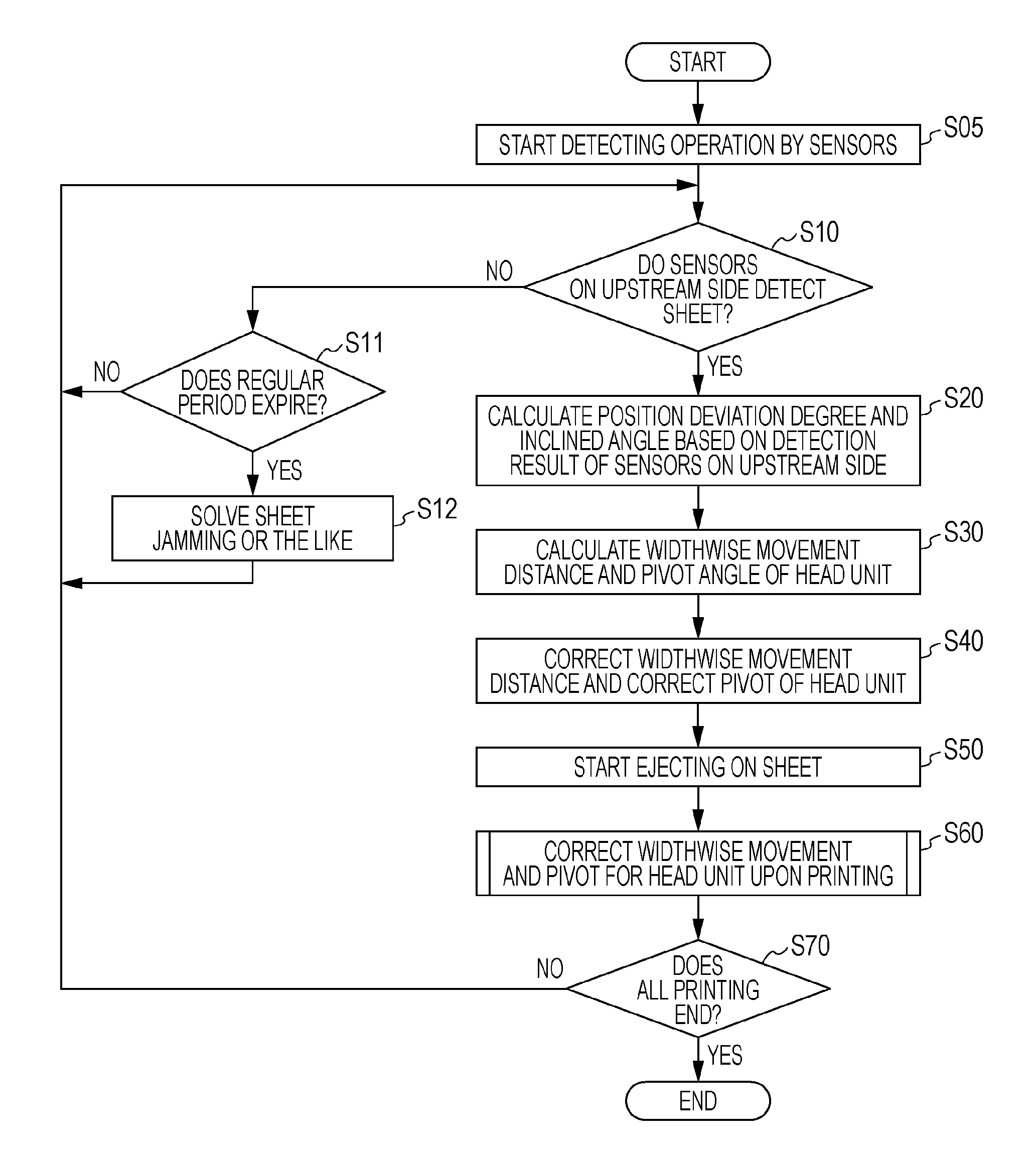
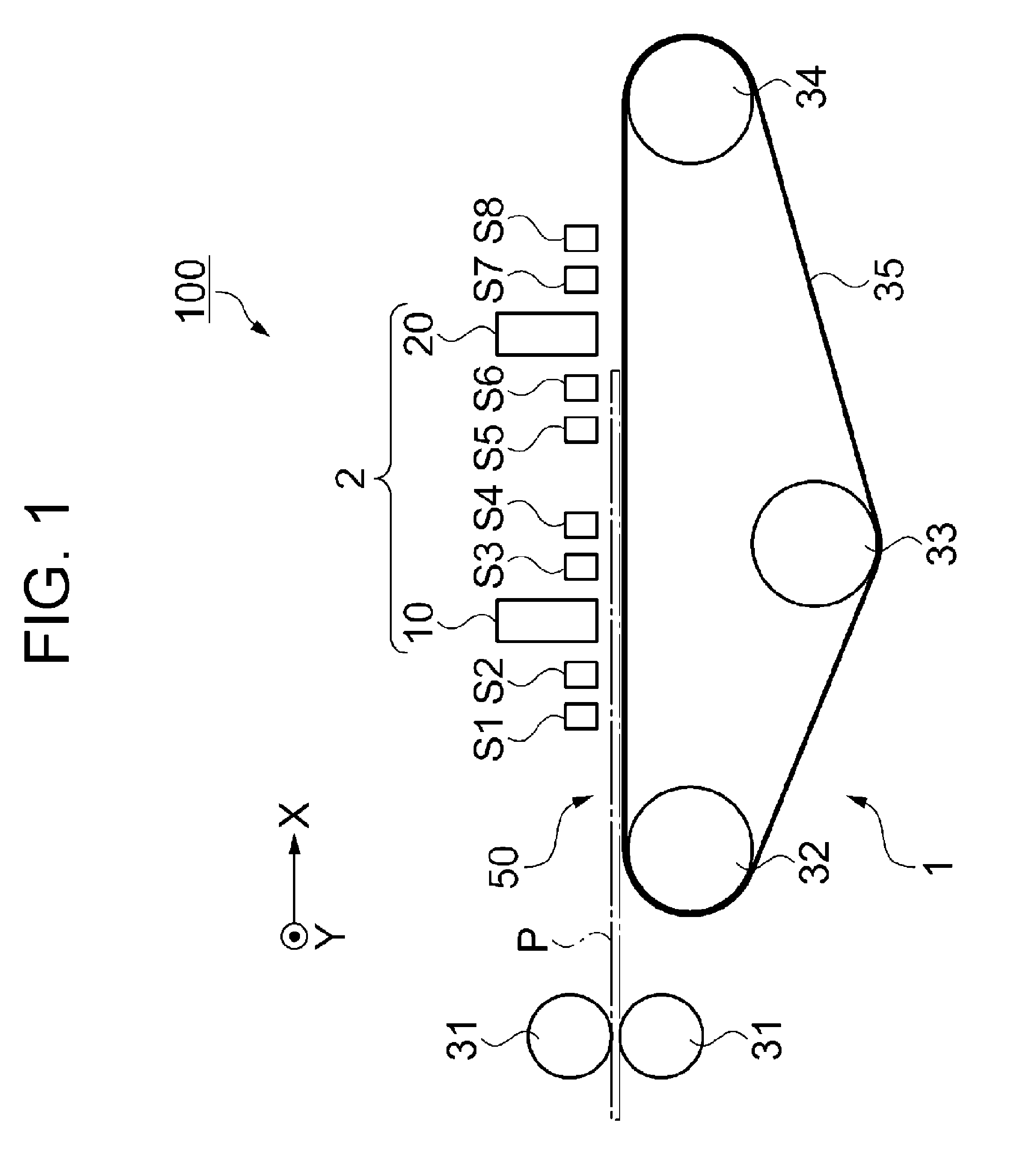
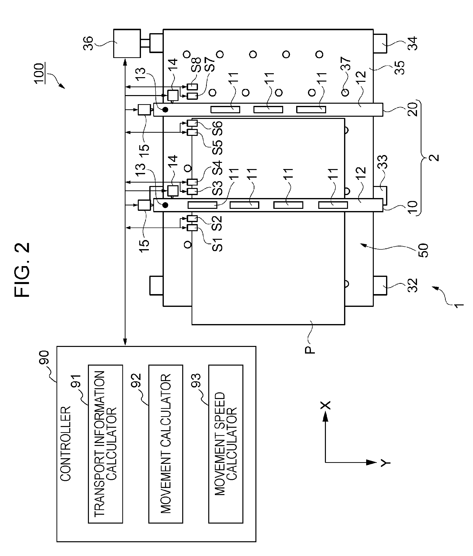
[0039]Hereinafter, as an example of a printing apparatus including a print position correcting device and performing printing on a print medium, an ink jet printer according to a first embodiment which prints an image on a print medium such as a sheet by jetting (ejecting) a liquid such as ink will be described. Here, the ink jet printer is a line head type ink jet printer capable of performing printing by so-called one pass in that the ink jet printer includes two head units mounted with a plurality of ink jet heads (ejecting heads) in a direction intersecting a sheet transport direction.

[0040]FIG. 1 is a side sectional view schematically illustrating the overall configuration of an ink jet printer 100 according to the first embodiment. FIG. 2 is a plan view schematically illustrating the overall configuration of the ink jet printer 100. As shown in FIGS. 1 and 2, the ink jet printer 100 includes a transport mechanism 1 for holding and transporting a sheet P to be printed and a pri...

second embodiment

[0131]Next, an ink jet printer 200 according to a second embodiment will be described. Here, the same reference numerals are given to the same constituent elements as those of the first embodiment, and the detailed description is omitted.

[0132]The ink jet printer 100 according to the first embodiment and the ink jet printer 200 according to the second embodiment are different from each other in the mechanism and operation associated with the movement and pivot of the head units 10 and 20 and the arrangement of the sensors detecting the position of the sheet P. FIG. 9 is a plan view schematically illustrating the overall configuration of the ink jet printer 200 according to the second embodiment. FIGS. 10A and 10B are explanatory diagrams illustrating the mechanism and the operation associated with the reciprocating movement and pivot of the head unit 10 according to the second embodiment. Here, the head unit 10 will be described, but the same is applicable to the head unit 20.

[0133]...

modified examples

[0144]In the above-described embodiments, one common transport mechanism 1 is provided for two head units, the head units 10 and 20, as shown in FIG. 1 and the like. However, the invention is not limited thereto. For example, FIG. 11 is a side sectional view schematically illustrating the overall configuration of an ink jet printer 300. The ink jet printer may have a tandem type configuration in which an independent transport mechanism 1 is provided for each of the head units 10 and 20.

[0145]The plurality of ejecting heads 11 is separated and arranged in the two head units 10 and 20. However, the invention is not limited thereto. For example, only one head unit may be disposed in the ink jet printer and all of the ejecting heads may be arranged in the head unit.


PUM


Abstract

A print position correcting device includes: a head unit which ejects a liquid onto a print medium being transported on a transport surface; detectors which detect a position of the print medium being transported; a transport information calculator which calculates transport information regarding a transport status of the print medium based on the position of the detected print medium; a movement speed calculator which calculates a movement speed used to move the head unit based on the transport information; and a controller which moves the head unit in a direction parallel to the transport surface based on the transport information and the movement speed.

Description

BACKGROUND[0001]1. Technical Field[0002]The present invention relates to a print position correcting device, a method of controlling the print position correcting apparatus, and a printing apparatus.[0003]2. Related Art[0004]In the past, there have been suggested various techniques for ejecting a liquid from a head unit onto exact positions on a print medium being transported in a printing apparatus such as an ink jet printer. For example, in an ink jet printer disclosed in JP-A-8-230194, ejection timing is corrected by detecting the transport speed of a print medium in order to land liquid droplets onto the exact positions on the print medium of which the transport speed is not uniform. In addition, in an ink jet printer disclosed in JP-A-2008-12712, the alignment of a line head is automatically adjusted with high precision to prevent a print defect such as an oblique line caused due to an alignment error of the line head.[0005]In the ink printer disclosed in JP-A-8-230194, however...

Claims


Application Information

Patent Timeline
Patent Type & Authority Patents(United States)
IPC IPC(8): B41J29/38B41J29/393
CPCB41J3/543B41J13/0027B41J19/202B41J2/2146B41J25/001B41J25/003
Inventor ENOMOTO, KATSUMI
Owner SEIKO EPSON CORP
Why Eureka
Try Eureka