Electrical connector assembly having electrical connector with low profile and processor with cone pins

a technology of electrical connectors and connector assemblies, which is applied in the direction of coupling contact members, fixed connections, coupling device connections, etc., can solve the problems of increasing the number of contacts, increasing the force exerted on the processor, and difficulty in assembling the processor, etc., and achieves the effect of low profil

Inactive Publication Date: 2012-05-08
HON HAI PRECISION IND CO LTD
View PDF12 Cites 56 Cited by
  • Summary
  • Abstract
  • Description
  • Claims
  • Application Information

AI Technical Summary

Benefits of technology

[0007]An object of the invention is to provide a low profile electrical connector and can protect the pin of the processor.

Problems solved by technology

However, the number of the contacts becomes more and more, and the force that exerts on the processor becomes larger and larger.
Thus, it is difficult to assemble the processor and the pin is easily deformed.
However, the cover and the lever occupy more space, which violates the development trend of the minimization of the electrical connector.

Method used


Image

  • Electrical connector assembly having electrical connector with low profile and processor with cone pins
  • Electrical connector assembly having electrical connector with low profile and processor with cone pins
  • Electrical connector assembly having electrical connector with low profile and processor with cone pins

Examples


first embodiment

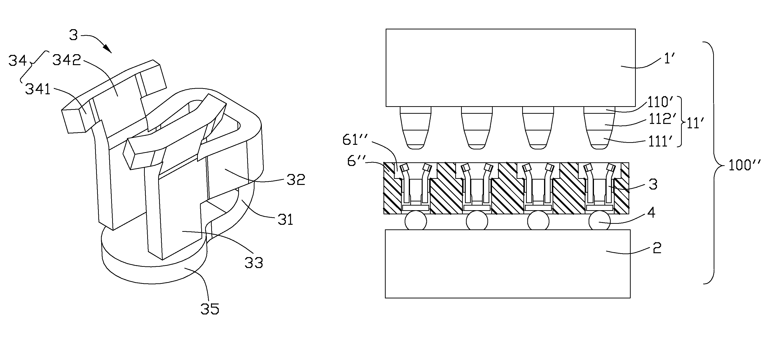
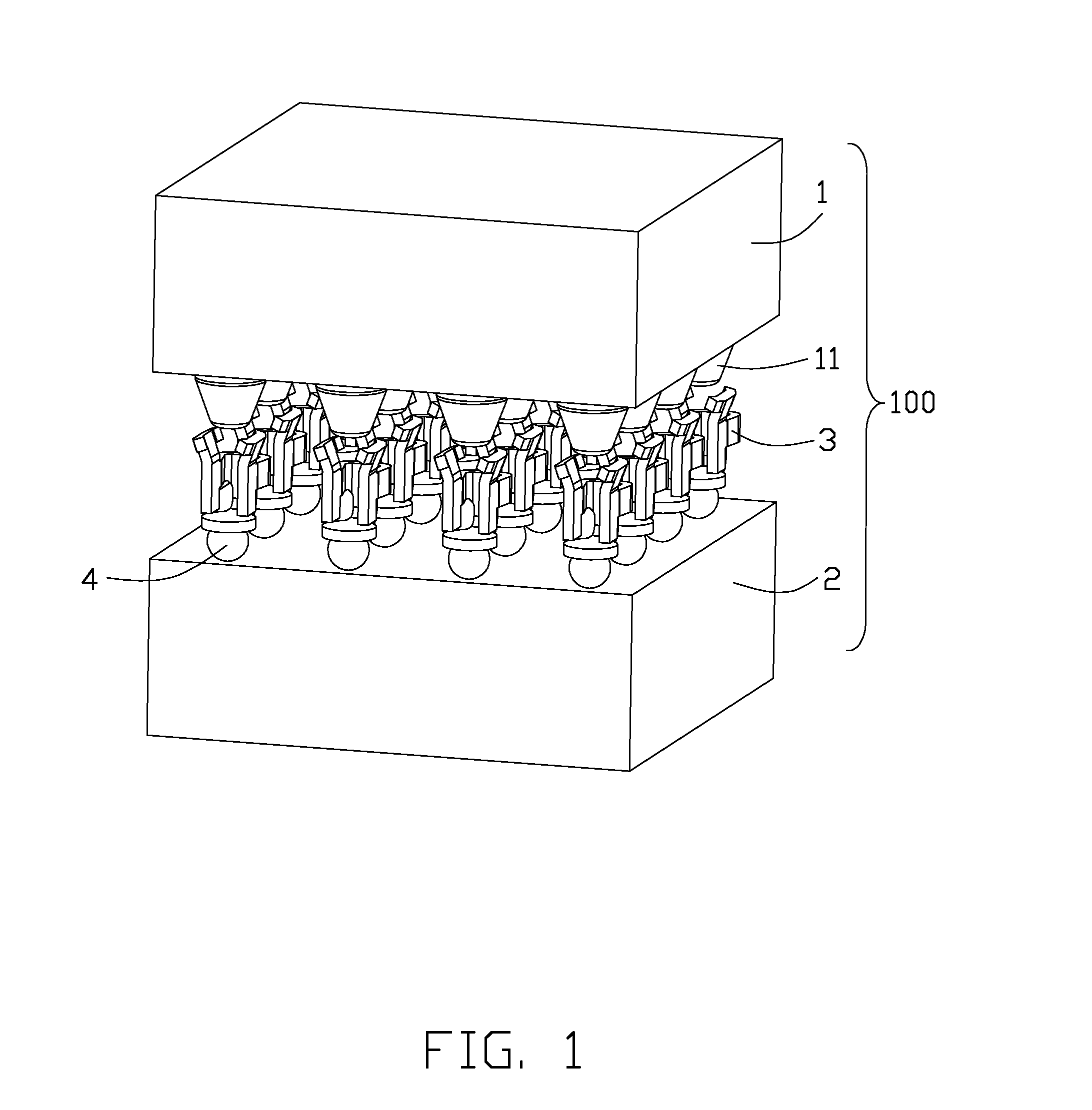
[0023]Referring to FIGS. 1-3, an electrical connector assembly 100 in accordance with the present invention comprises a substrate 2, a plurality of contacts 3 soldered to the substrate 2 by solder balls 4 and a processor 1. The processor 1 includes a plurality of pins 11 connecting with the contacts 3. The pin 11 comprises a cone portion 111 at a bottom end thereof and a cylinder portion 110 at a top end thereof. The bottom of the cone portion 111 is thinner than the top thereof. Referring to FIG. 4, an alternative embodiment to FIG. 3, the electrical connector assembly 100 also comprises an insulative housing 6 with a plurality of passageways 61, the contacts 3 are received in the passageways 61.

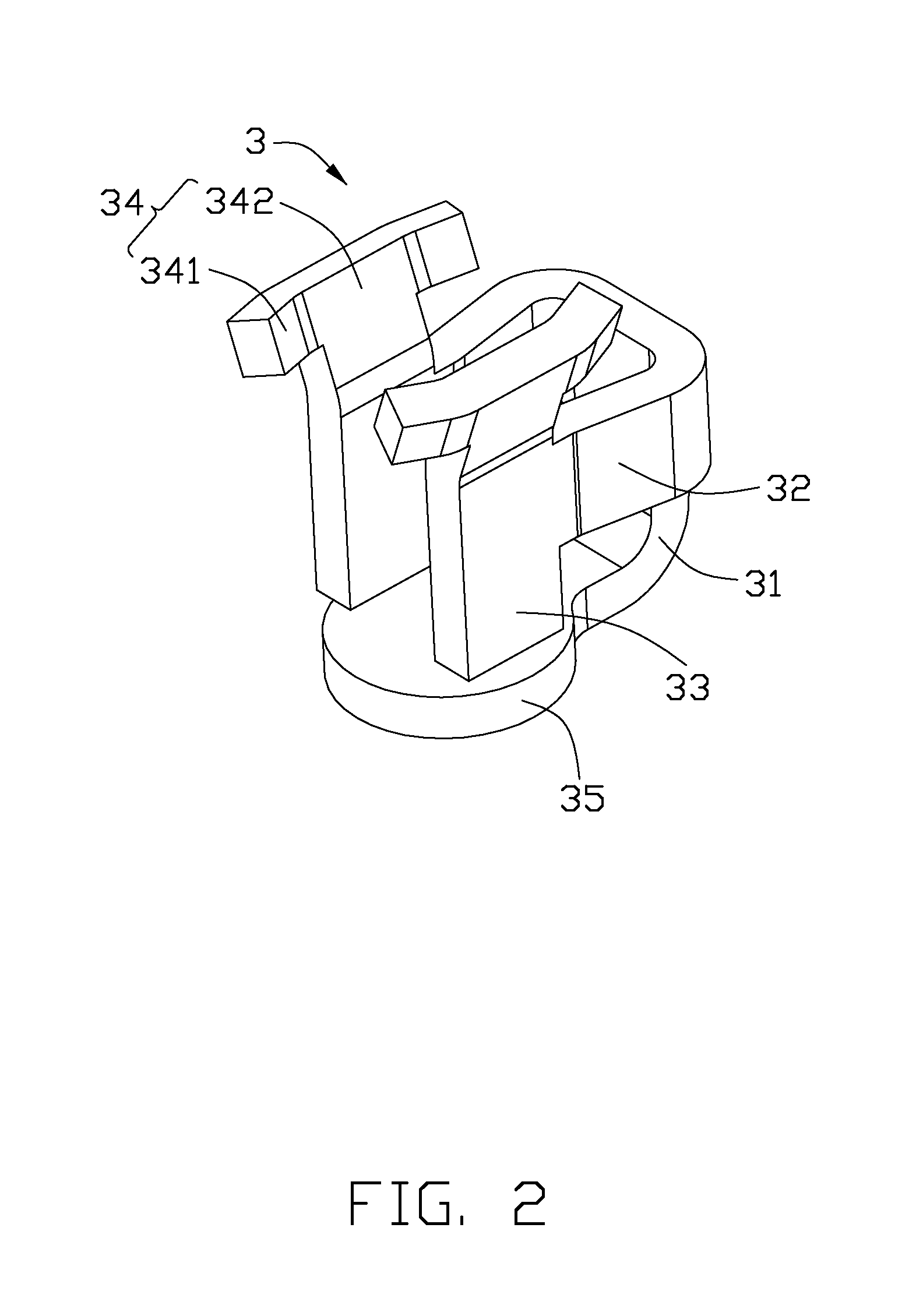
[0024]Referring to FIG. 2, the contact 3 comprises a base portion 31, a pair of connecting portions 32 extending from opposite sides of the base portion 31, a pair of stopper portions 33 extending downwardly from the connecting portions 32, a pair of contacting portions 34 extending upwardl...

second embodiment

[0026]Referring to FIGS. 6-9, which shown an electrical connector assembly 100′ according to a The contact 5 is configured to a column shape with a through hole 53 impenetrate therethrough. The contact 5 defines a slot 54 to form a pair of contacting portions 52 at the upper end and a pair of spring arms 51 at the lower end. The contacting portions 52 each defines a chamfer portion 521. In this embodiment, the through hole 53 is larger than the bottom end of the pin 11 and is smaller than the top end thereof. When the processor 1 is assembled to the contact 5, the bottom end of the pin 11 is inserted into the through hole 53 with lower insertion force. Referring to FIG. 7, which discloses an alternative embodiment to FIG. 6, the electrical connector assembly 100′ also comprises an insulative housing 6′ with a plurality of passageways 61′, the contacts 5 are received in the passageways 61′.

[0027]When the processor 1 is assembled to the contact 5, the bottom end of the cone portion 1...


PUM


Abstract

An electrical connector assembly (100) for mounting to a printed circuit board, comprises a plurality of contacts (3) and a processor (1), the contact (3) comprises a base portion (31), a pair of contacting portions (34) and a solder portion (35) extend from the base portion (31), the processor (1) comprises a plurality of pins (11) each includes a cylinder portion (110) and a cone portion (111) extending downwardly from the cylinder portion (110), the bottom end of the cone portion (111) is thinner than the top end thereof to guiding the pins (11) inserted into the contacts (3), the contacting portions (34) contacts with the cone portion (111) respectively.

Description

BACKGROUND OF THE INVENTION[0001]1. Field of the Invention[0002]The present invention relates to an electrical connector assembly, especially to an electrical connector assembly having electrical connector with low profile and processor having cone pins to make it be assembled to the electrical connector with little force.[0003]2. Description of the Related Art[0004]U.S. Pat. No. 6,135,784 issued to Pei on Oct. 24, 2000 discloses a LIF Pin Grid Array (PGA) electrical connector. The electrical connector comprises an insulative housing with a plurality of contacts received therein and a processor assembled on the insulative housing. The processor includes a plurality of pins connecting with the contacts. The contact comprises a pair of spring arms. When the processor is assembled to the insulative housing, the pin of the processor exerts a force on the two spring arms pushing the spring arms move away from each other, and finally the pin connect with the spring arms. Thus, an electric...

Claims


Application Information

Patent Timeline
Patent Type & Authority Patents(United States)
IPC IPC(8): H01R13/64
CPCH01R12/718H01R12/57
Inventor WERTZ, DARRELL LYNN
Owner HON HAI PRECISION IND CO LTD
Why Eureka
Try Eureka