Wheelchair base

a technology for wheelchairs and wheels, applied in the field of wheelchairs, can solve the problems of wheelchairs having reduced stability, uneven weight distribution among casters, and adding to user discomfort, so as to achieve uneven weight distribution, improve comfort, and dampen irregularities and vibrations

Active Publication Date: 2012-05-15
DUGAS ERIC +1
View PDF29 Cites 46 Cited by
  • Summary
  • Abstract
  • Description
  • Claims
  • Application Information

AI Technical Summary

Benefits of technology

[0016]Advantageously, the proposed wheelchair base allows for manufacturing a wheelchair in which the four auxiliary wheels and the two drive wheels can simultaneously remain in contact with the ground while travelling, even if the ground includes relatively large irregularities. This is due, in part, by the ability of the first and second pivot arm assemblies to pivot independently of each other relative to the base frame. This in turn greatly increases the stability of the wheelchair, which is particularly advantageous in the case of motorized wheelchairs that are often used by intended users having restricted strength, and which, therefore, cannot use their strength to stabilize the wheelchair should any wheel get out of contact with the ground.
[0021]a) which may be used to travel over uneven or undulated ground surfaces, with each of its wheels maintaining permanent contact with the ground, as well as supporting an evenly distributed load;
[0022]b) whose auxiliary and drive wheels, being all mounted on pivot arms relative to the base frame, substantially dampen irregularities and vibrations encountered on the ground surface that are communicated to the base frame supporting the seat assembly and, thus, provide a more comfortable ride to the user of the wheelchair;
[0023]c) whose base frame allows for independent positioning of the seat assembly and battery compartment relative to the longitudinal axis of the motorized base, thus allowing a user to adjust the seat assembly to a preferred longitudinal position relative to the motorized base, while still preserving the overall center of gravity of the wheelchair generally above the drive wheels through the independent adjustment of the battery compartment;
[0024]d) which is quite simple and inexpensive in construction, and yet which is quite efficient and reliable in operation.

Problems solved by technology

a) the generally limited flexibility of the suspension systems integrated in motorized bases of the prior art, particularly the suspension systems comprising resilient material such as rubber, instead of dynamic suspension strut, often result in a wheelchair experiencing uneven distribution of weight among its casters and drive wheels when engaging on an uneven or undulated ground surface. In some situations, one or more of the casters or drive wheels loose contact with the ground, thus resulting in a wheelchair having reduced stability;
b) moreover, while most motorized bases incorporates some form of suspension means applied to the front casters and / or drive wheels, the rear or anti-tip casters are generally rigidly attached to the rear end of the base frame and, thus, any small projections or irregularities encountered on the ground surface are directly transmitted to the seat and backrest assembly, adding to the discomfort of the user;
c) motorized bases equipped with pivotabie front casters and drive wheel assemblies may prove hazardous to use, particularly on an uneven or undulated ground surface since one or both front casters may inadvertently leave the ground due to a forced acceleration applied during a climbing operation;
d) generally, the inherent structure of the motorized bases does not allow for the custom positioning of the seat assembly and / or the battery compartment along the longitudinal axis of the central base frame, thus constraining the user to adopt a fixed position over a predefined center of gravity of the wheelchair.

Method used


Image

  • Wheelchair base
  • Wheelchair base
  • Wheelchair base

Examples


Embodiment Construction

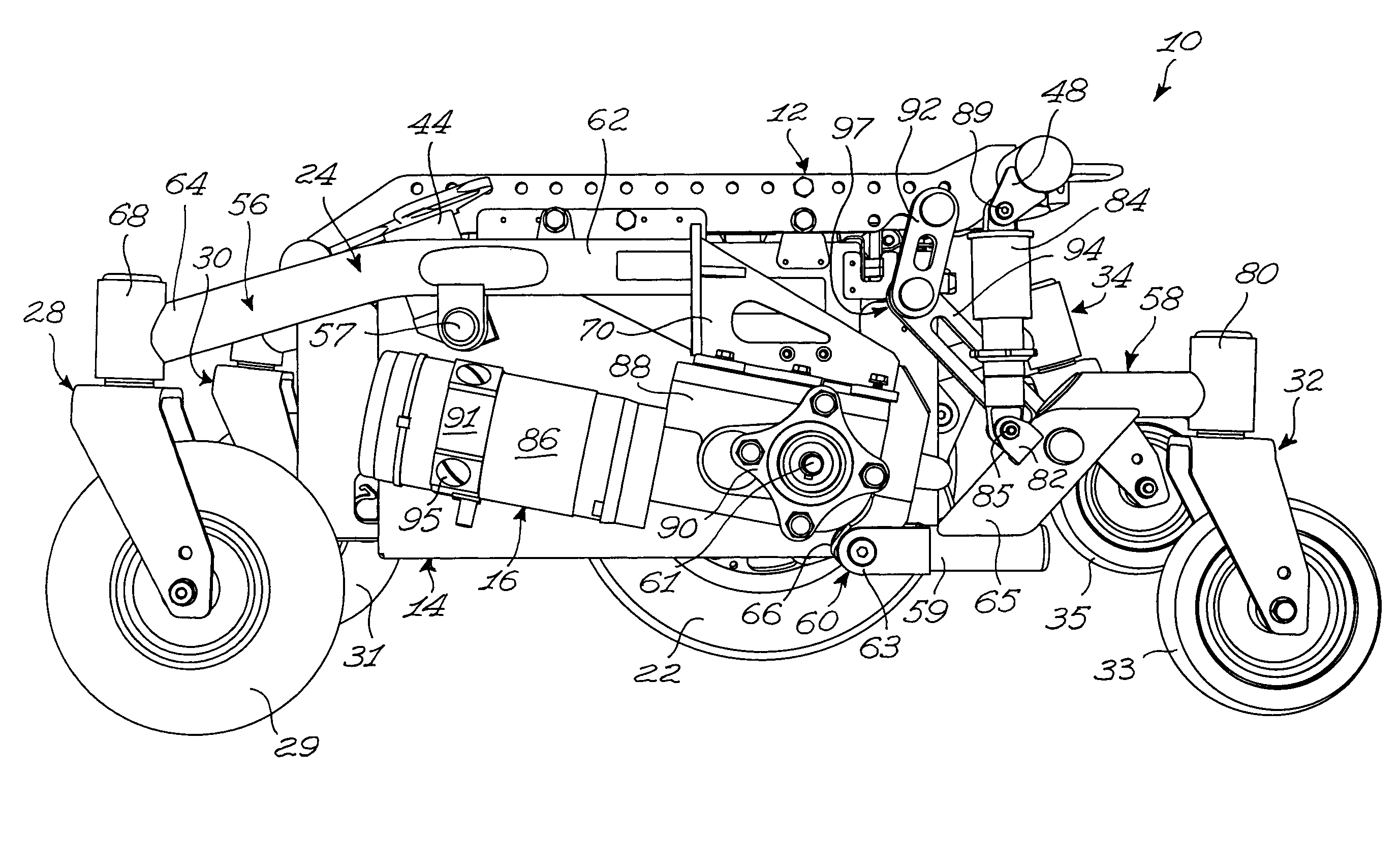
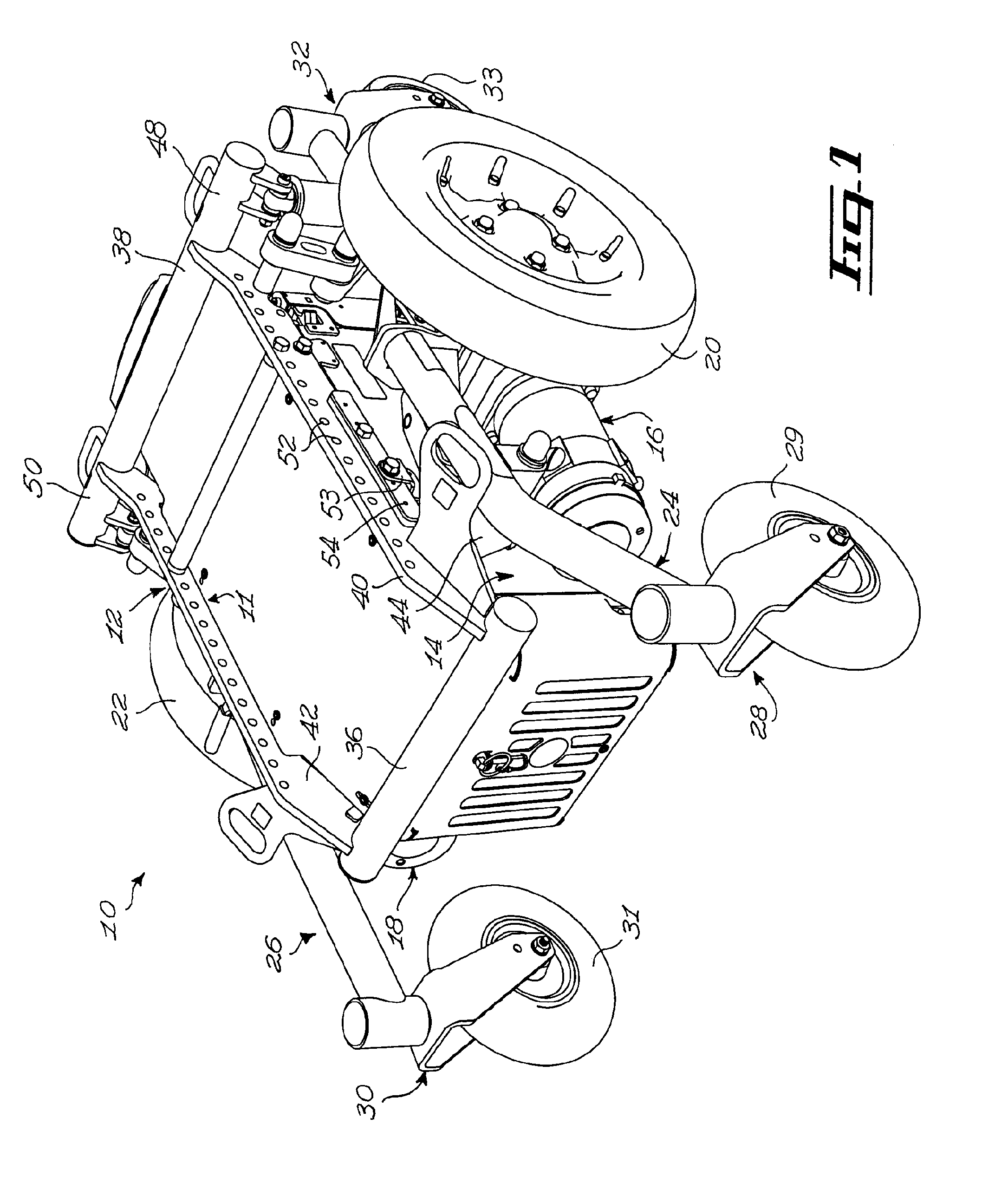
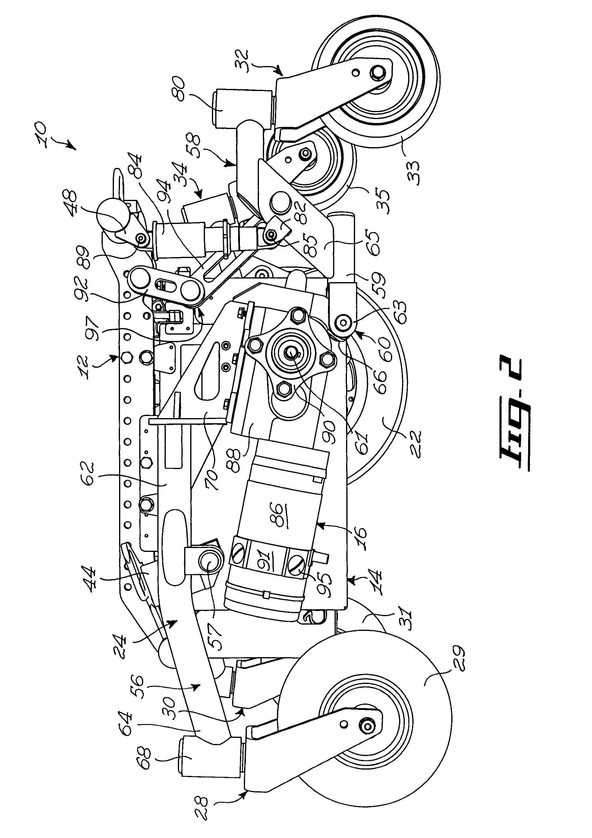
[0044]FIGS. 1 to 4 show various aspects of an embodiment of a wheelchair base 10 in accordance with an embodiment of the present invention. For example, the wheelchair base 10 is a base for a mid-wheel power drive wheelchair. Referring to FIG. 1, the wheelchair base 10 generally comprises a chassis 12, a battery compartment 14, two mid-wheel power drive assemblies 16 and 18, to which respectively first and second drive wheels 20 and 22 are mounted, first and second pivot arm assemblies 24 and 26, front caster assemblies 28 and 30 including respectively front end first and second wheels 29 and 31, and rear caster assemblies 32 and 34 including respectively rear end first and second wheels 33 and 35, only one of which is seen in FIG. 1.

[0045]The reader skilled in the art will readily appreciate that the terminology “front” and “rear” is used to facilitate the description of the wheelchair base 10 and should not be used to restrict the scope of the invention. Indeed, some usable embodi...


PUM


Abstract

A wheelchair base including a base frame and a pair of pivot arm assemblies each including a first pivot arm and a second pivot arm, pivotally coupled to each other for pivotal movement about a transverse pivot axis. The pivot arms defining first and second auxiliary wheel attachments opposed to the transverse pivot axis for attaching first and second end auxiliary wheels. Each pivot arm assembly including a link pivotally coupled to the second pivot arm intermediate the transverse pivot axis and the second auxiliary wheel attachment for pivotal movement about a link axis substantially parallel to the transverse pivot axis forming a drive wheel attachment intermediate the auxiliary wheel attachments. The pivot arm assemblies are mounted to the base frame substantially laterally opposed to each other through the link and first pivot arm such that the pivot arm assemblies are independently pivotable relative to the base frame.

Description

FIELD OF THE INVENTION[0001]The present invention relates generally to wheelchairs and, more particularly, to a wheelchair base, such as a motorized base for a mid-wheel power drive wheelchair.BACKGROUND OF THE INVENTION[0002]Mid-wheel power drive wheelchairs are known in the art and generally consist of a motorized base supporting a seat assembly. The motorized base generally comprises a central base frame equipped with a pair of drive wheels that are approximately positioned below the center of gravity of the vehicle when loaded with a user, a pair of front casters and a pair of rear, anti-tip casters, which prevent rearward tipping of the wheelchair. The pair of drive wheels are typically powered by individual compact electric motor and gearbox assemblies directly coupled to the inner side of each drive wheel, and a power battery conveniently tucked in a battery compartment generally occupying a central position between the drive wheels, just underlying the seat assembly.[0003]Th...

Claims


Application Information

Patent Timeline
Patent Type & Authority Patents(United States)
IPC IPC(8): B62D49/08A61G5/04
CPCA61G5/043A61G5/06A61G2005/1078A61G2005/1089Y10S180/908Y10S180/907A61G5/1078A61G5/1089
Inventor DUGAS, ERICLANDRY, CARMON
Owner DUGAS ERIC
Why Eureka
Try Eureka