
Appliance control knob providing illuminated setting indication

a technology of illumination and setting indication, applied in the direction of electrical switches, contact mechanisms, electrical apparatus, etc., can solve the problems of difficult operation of this type of rotation control in lowlight setting, and achieve the effect of improving light efficiency and simple and energy-saving

Active Publication Date: 2012-05-15
ILLINOIS TOOL WORKS INC
View PDF3 Cites 9 Cited by
  • Summary
  • Abstract
  • Description
  • Claims
  • Application Information

AI Technical Summary

Benefits of technology

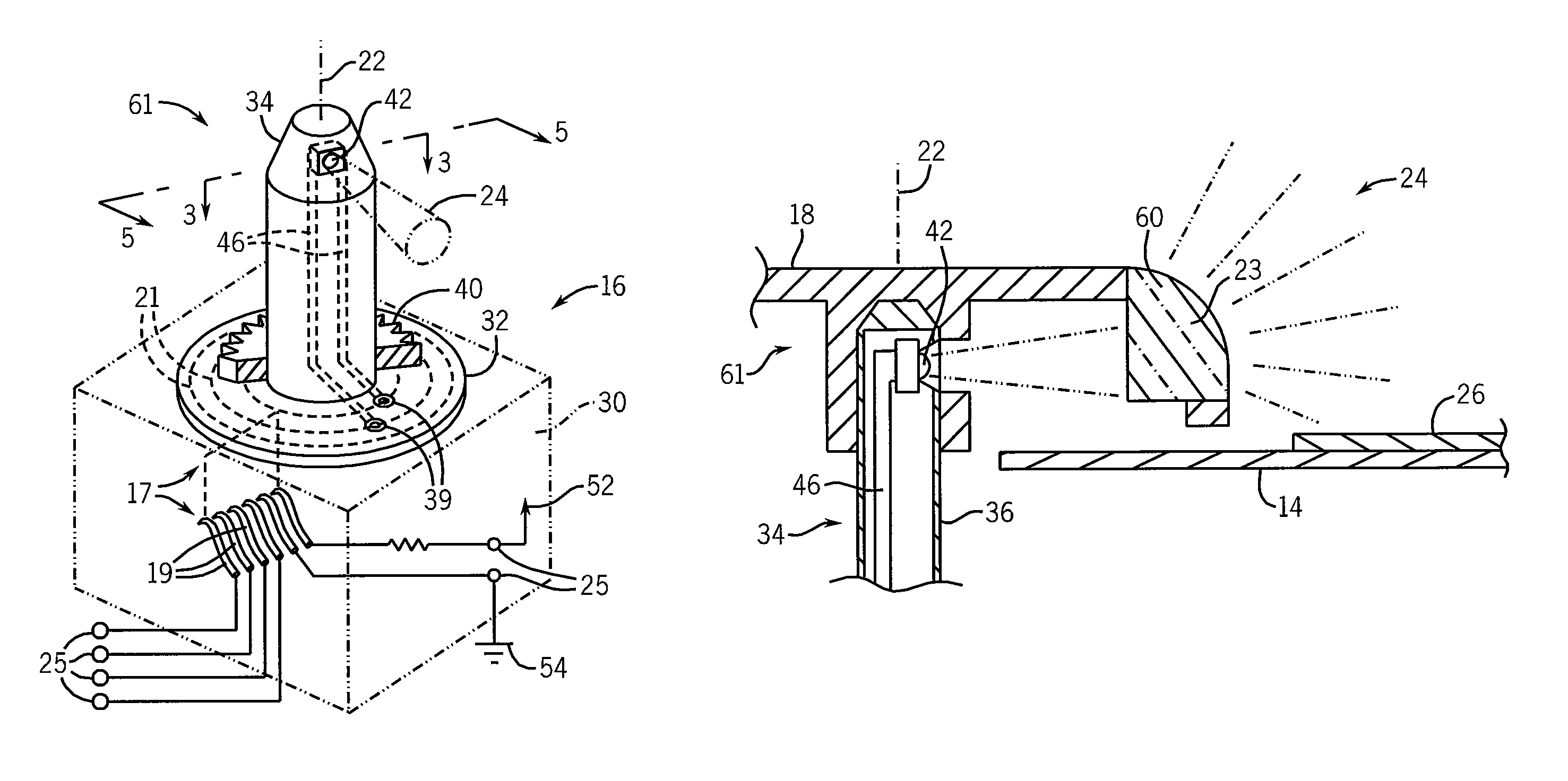
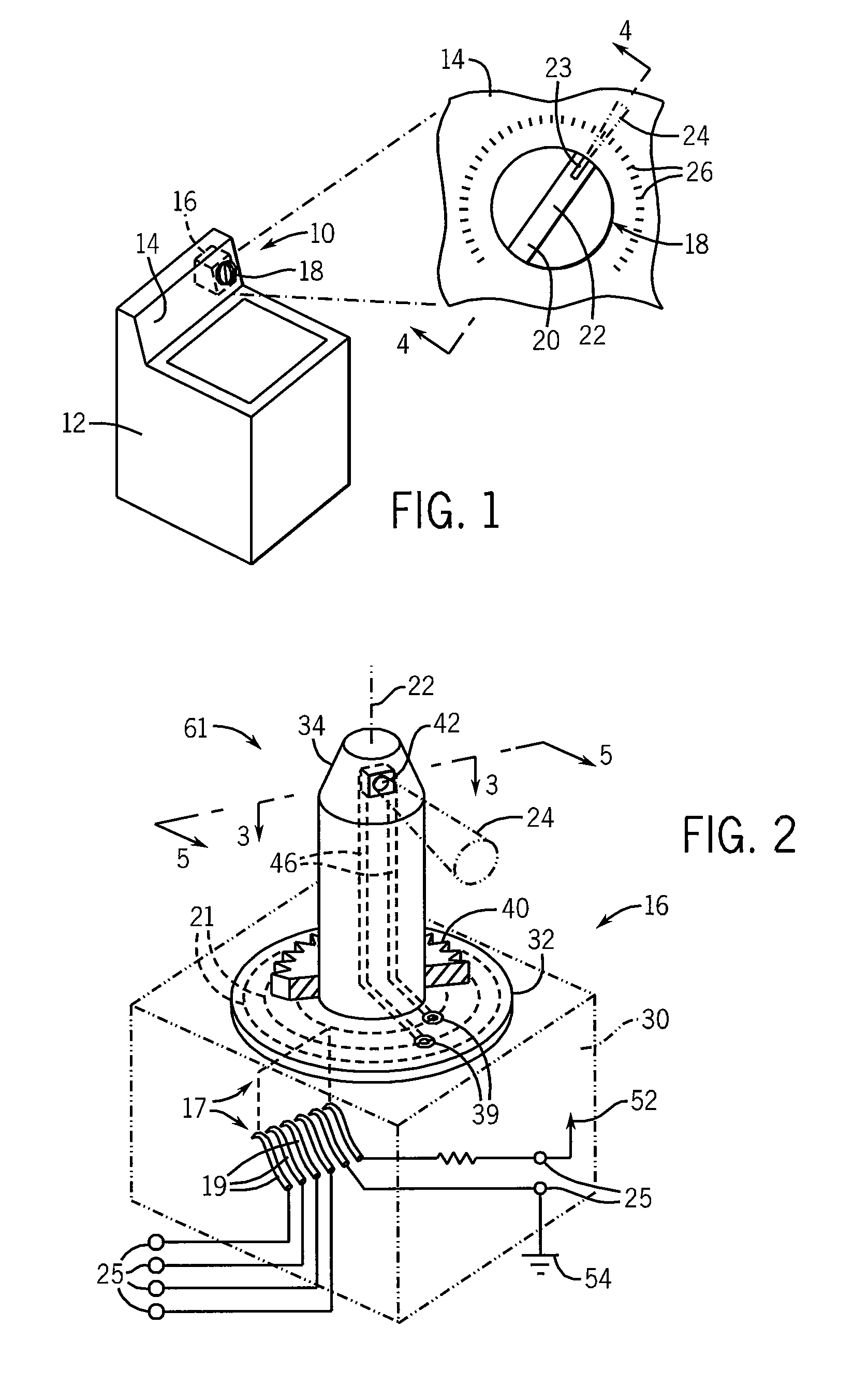
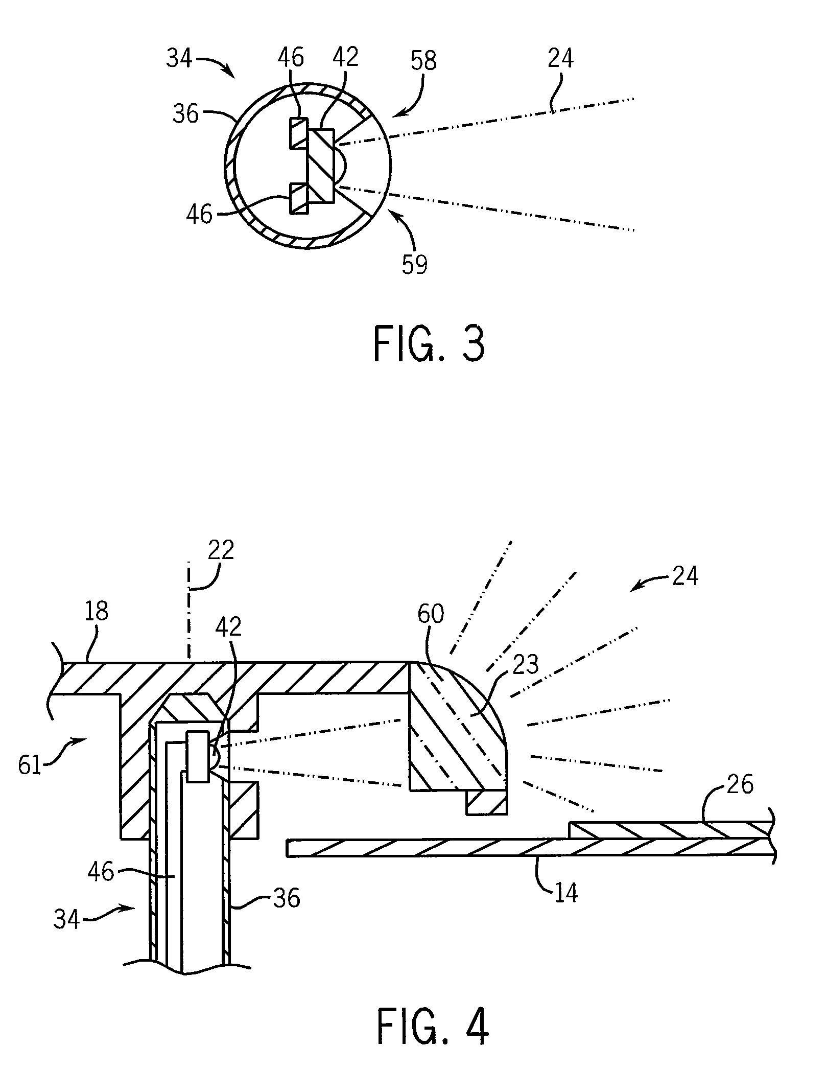
The present invention provides a simple and energy-efficient method of providing setting illumination when using standard electromechanical or electrical rotating knob controls such as found in a washing machine. By placing a light emitting diode (LED) at the end of the operator shaft receiving the control knob and utilizing sliding contacts to power the LED, improved illumination can be obtained with a rotating type control. The control can be used with different interchangeable knobs for different appliance models. The second light passageway may be a lens to further diffusion, focusing or collimation of the light from the LED. The technical effects of the invention include improved illumination in a free rotating control, simple power conditioning for powering the LED, and a controlled separation of electrical conductors to reduce the chance of user exposure to line voltage.

Problems solved by technology

Nevertheless, operation of this type of rotation control in lowlight settings can be difficult.

Method used


Image

  • Appliance control knob providing illuminated setting indication
  • Appliance control knob providing illuminated setting indication
  • Appliance control knob providing illuminated setting indication

Examples


Embodiment Construction

[0037]Referring now to FIG. 1, a washing machine 10 suitable for use with the present invention includes a housing 12, typically of enameled steel, having a front facing console 14 supporting a control 16 such as a cycle timer or the like. The washing machine 10 may include an internal spin basket, motor, and water-handling electromechanical valves (not shown) as understood in the art.

[0038]A control 16, for example a cycle timer, attaches in part behind the console 14 and provides a shaft 34 (not shown in FIG. 1) which passes through the console 14 and attaches to a knob 18, the latter which may be rotated to control the cycling of the washing machine 10 and which may also rotate during operation to indicate a current cycle stage.

[0039]The knob 18 may include a finger grip 20 that may be grasped by a user to rotate the knob 18 about a center axis 22. A transparent or translucent lens 23 may be exposed at one end of the finger grip 20 and may be internally illuminated (as will be de...


PUM


Abstract

A shaft of a rotary switch, for example, useful as a control for an appliance, such as a washing machine, incorporates an LED at the end of the shaft and projecting light laterally from the shaft to provide an indication of the rotary position of the corresponding knob with respect to printed indicia on a console. The LED may be powered by slip rings incorporated into the rotary switch and communicating directly with line power as controlled by the limiting resistor and the shaft may include a controlled breakage feature providing LED conductors that are recessed within the shaft in the event of shaft breakage to reduce the chance of operator contact with line voltage.

Description

CROSS-REFERENCED TO RELATED APPLICATIONS[0001]This application claims the benefit of U.S. Provisional Application Ser. No. 61 / 145,634 filed on Jan. 19, 2009 and hereby incorporated by reference.BACKGROUND OF THE INVENTION[0002]It is known to provide controls for common household appliances that provide an illuminated indication of their setting, for example, using LEDs, backlit LCDs, or plasma type displays. Such illuminated controls are aesthetically attractive, allow the appliance to be easily used in low light areas, and provide an indication of their setting visible at a distance.[0003]Present electrical and electromechanical controls for washing machines and the like provide an operator knob having a pointer, for example an embossed line or arrow, that may be rotated into alignment with preprinted indicia indicating the control's setting. Often the indicia are printed on an opaque, enameled metal sheet. A rotational control of this type is both familiar and provides an intuitiv...

Claims


Application Information

Patent Timeline
Patent Type & Authority Patents(United States)
IPC IPC(8): H01H9/00
CPCH01H19/025
Inventor LARSON, ERIC K.BARRENA, JUAN J.MACDONALD, JR., JAMES J.ROMO, MARK A.TUCKER, ANDY W.
Owner ILLINOIS TOOL WORKS INC
Learn More