Point of use water purification method & apparatus

a technology of water purification method and apparatus, which is applied in the direction of vacuum distillation separation, separation process, vessel construction, etc., can solve the problems of inability to completely eliminate, biofilm can be reduced, and problems still exist, and achieve the effect of quick and easy removal

Inactive Publication Date: 2005-02-24
ENVIRONMENTAL TECH ENTERPRISES
View PDF14 Cites 9 Cited by
  • Summary
  • Abstract
  • Description
  • Claims
  • Application Information

AI Technical Summary

Benefits of technology

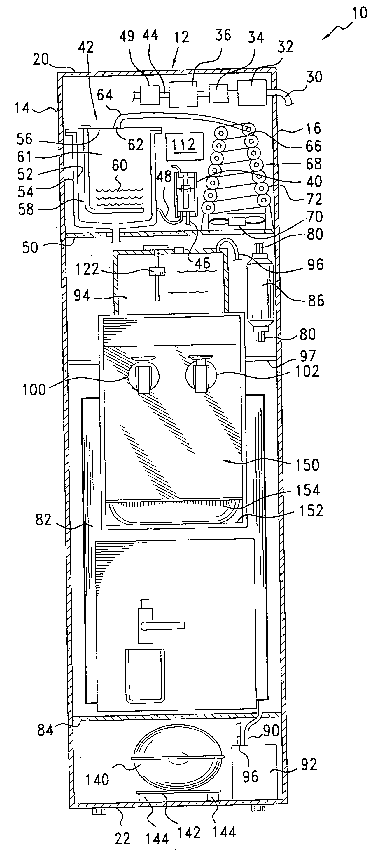
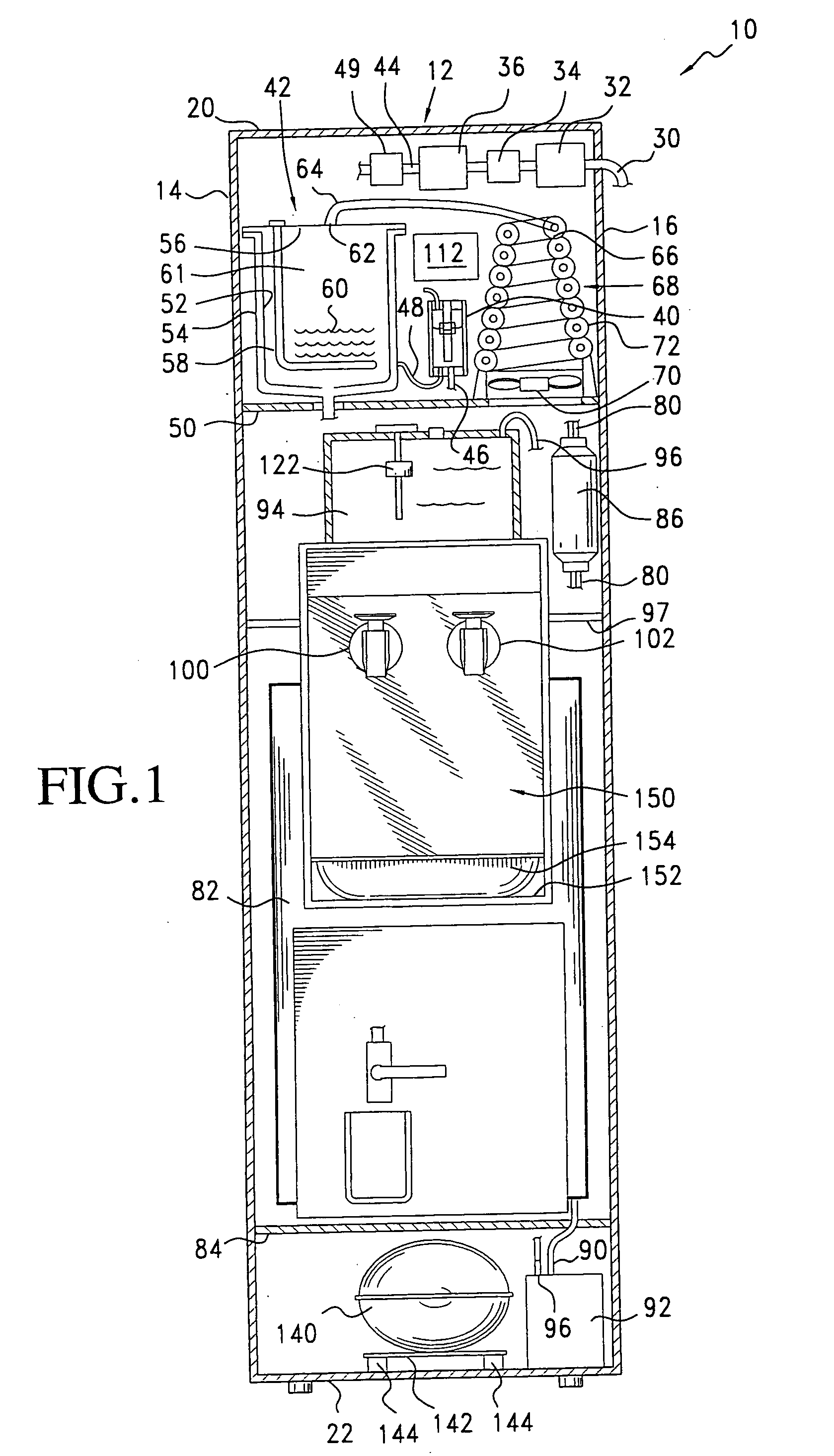
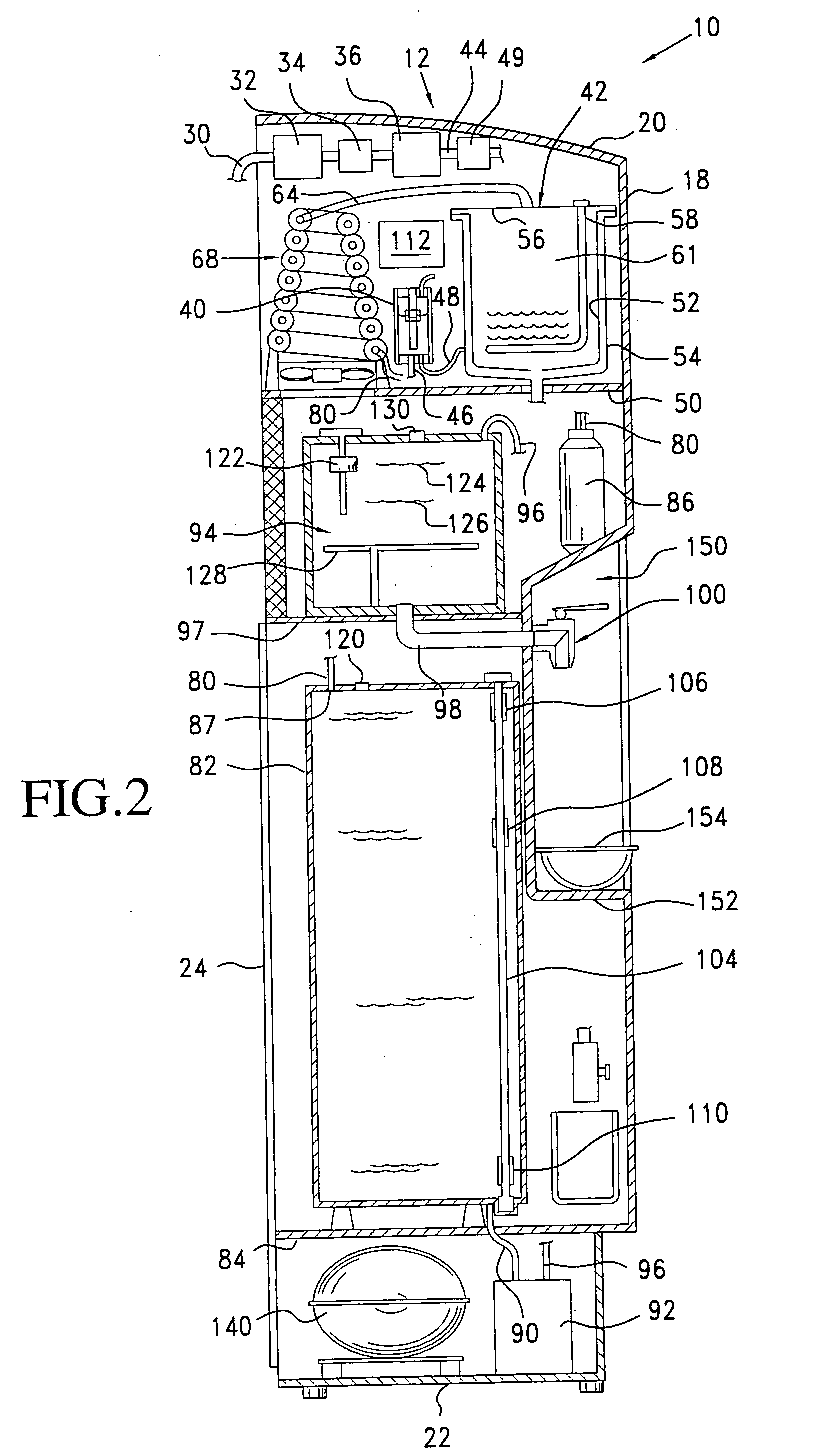
[0031] The distiller of the present invention may be a stand-alone floor unit, or may be configured as a portable counter-top batch or continuous flow distillation apparatus having a completely open top for quick and easy removal and cleaning of the boiler and a heat source that never has to be cleaned. Th

Problems solved by technology

Many products, including water distillation devices, have been developed in attempts to provide safe water for drinking, but problems still exist.
Research has shown that biofilming can be reduced by timely and critical maintenance, but it cannot be completely eliminated and backflushing may contaminate the system.
Ultraviolet (UV) water purification systems only address the problem of microbial contamination, and do not remove other contaminants from water.
Furthermore, changing turbidity conditions in the water reduces the ability of such systems to kill microbes.
However, difficulties have been encountered in the development of acceptable point of use distillers, and these problems have prevented their widespread use.
A common problem in prior art distillers is the difficulty involved in properly cleaning the boiler, for it usually is difficult to get to the boiler and difficult to clean scale from its interior.
The buildup of scale in the boiler tanks of distillers is partially due to the fact that untreated influent water contains bicarbonate ions which will initially break down into carbonate ions, causing the formation of scale.
Partial, instead of complete, draining of the boiler can also reduce scale buildup, but periodic cleaning is still required and the construction of most prior distillers have made the cleaning process so complicated that the distiller gradually becomes less efficient.
Although numerous attempts have been made to facilitate the descaling and cleaning of distillers, the problem has not been completely solved, for most such attempts have resulted in additional plumbing requirements or additional components

Method used


Image

  • Point of use water purification method & apparatus
  • Point of use water purification method & apparatus
  • Point of use water purification method & apparatus

Examples


third embodiment

[0081] the noninvasive liquid level sensor controller detector of the present invention is illustrated at 380 in FIG. 11. This sensor is useful for noninvasively controlling, maintaining and detecting desired predetermined liquid levels in an associated vessel such as the boiler vessel 42, as discussed above, but in this case, the sensor 380 is used in association with a vessel or container which operates at pressures other than atmospheric. The illustrated device is similar to that illustrated in FIG. 9, and accordingly similar elements carry similar reference numerals. In this case, however, the vent tube 334 of the device of FIG. 9 is replaced by a pressure tube connector 382 which extends through the top cap 302 of sensor 380 and is in communication with the interior 308 of the body 300. The connector 382 is connected by way of pressure equalizer tube 384 to the uppermost portion 386 within vessel 42, above the upper level 320 of the liquid 60 within the vessel, by way of a conn...

fourth embodiment

[0082] the liquid level sensor of the present invention is illustrated in FIG. 12, to which reference is now made. In this embodiment, a level sensor and controller 400 is associated with a vessel or container 402, which may be the boiler vessel 42 of the present invention. This embodiment differs from that of FIGS. 9 and 11 in that it permits a rapid flow rate for the introduction of liquid into the vessel 402, and is also suitable for use when the supply liquid is to be introduced into the vessel above the liquid level within the container. In this embodiment, the sensor 400 is similar to that of the previous figures and includes a two-level reed switch assembly 404, similar to that illustrated at 312 in FIG. 9., and a connector line 406 which connects the bottom of the sensor 400 to the bottom of vessel 402, so that the sensor 400 and the vessel 402 are interconnected at locations below the desired minimum water level 408. The sensor is vertically aligned with vessel 402 so that ...

fifth embodiment

[0086] the noninvasive liquid level sensor and controller of the present invention is illustrated in FIG. 13, to which reference is now made. The sensor 450 of FIG. 13 differs from the embodiment illustrated in FIG. 9 only in that water from solenoid outlet line 44 does not travel through sensor 450 but rather to an inlet 452 of a ‘T’ connector 454, then to sensor 450 by way of ‘T’ outlet 456, and to vessel 54 through ‘T’ outlet 458 and line 460. This embodiment may be particularly suitable when the heat exchanger 49 (FIG. 4) is utilized to avoid a potential increase in the cost of materials needed to allow the sensor 450 to accommodate heated influent water from the heat exchanger.

[0087] The water treatment process of the present invention as described above is illustrated diagrammatically in FIG. 14, wherein raw water to be treated passes through pre-filter 32, solenoid valve 36, and through heat exchanger 49 to boiler 42 and to sensor 40. At the same time, vapor from boiler 42 pa...


PUM

PropertyMeasurementUnit
Pressureaaaaaaaaaa
Responsivityaaaaaaaaaa
Energyaaaaaaaaaa

Abstract

A compact, energy efficient, continuous-flow point of use distillation system utilizes stacked, vertically-arranged components to provide a compact and energy efficient distillation process and a device which is quick and easy to service and maintain. A housing contains a double-walled boiler vessel to which water is supplied from an external source through suitable filters. A heating source is provided to boil water in the vessel, producing steam which is supplied through a condenser to a storage container located below the boiler. A noninvasive liquid level sensor maintains the water level in the boiler and the controller is provided to activate the boiler when water is required for the storage reservoir.

Description

[0001] This application claims the benefit of U.S. Provisional Application No. 60 / 326,226, filed Oct. 2, 2001, and of U.S. Provisional Application No. 60 / 344,809 filed Jan. 7, 2002, the disclosures of which are hereby incorporated herein by reference.BACKGROUND OF THE INVENTION [0002] The present invention relates, in general, to point-of-use distillation systems, and more particularly to compact, continuous-flow distillers for the purification of drinking water. [0003] The global need for safe drinking water is commonly recognized, for the health problems resulting from chemicals, bacteria and viruses in drinking water has been well documented. Many products, including water distillation devices, have been developed in attempts to provide safe water for drinking, but problems still exist. For example, reverse osmosis (RO) point of use water purification systems have limited and unsustainable contaminant removal, can allow the formation of biofilm on filter membranes, and produce wa...

Claims


Application Information

Patent Timeline
IPC IPC(8): B01D1/00B01D3/02B01D3/42B01D5/00C02F1/04F28D1/047F28D7/02
CPCB01D1/0017B01D3/42B01D5/0006B01D5/0084Y10S203/08C02F2209/42F28D1/0472F28D7/028Y10S203/11C02F1/04
Inventor LAND, GLENN E.
Owner ENVIRONMENTAL TECH ENTERPRISES
Why Eureka
Try Eureka