Battery charger using the phase shift by a pair of forward converting circuits

a technology of forward conversion circuit and battery charger, which is applied in the direction of ac-ac conversion, dc-dc conversion, transportation and packaging, etc., can solve the problems of circuit with oversized components and lack of efficiency

Active Publication Date: 2012-05-15
ILLINOIS TOOL WORKS INC
View PDF19 Cites 19 Cited by
  • Summary
  • Abstract
  • Description
  • Claims
  • Application Information

AI Technical Summary

Benefits of technology

[0004]The present disclosure provides a novel technique for dynamically adjusting an output voltage for a battery charging operation designed to respond to such needs. The technique allows for varying output voltage at the battery charger by manipulating the duty cycles of two forward converter circuits. In particular, the present disclosure provides methods and systems for increasing synchronized duty cycles in a pair of forward converter circuits in response to a changing battery charge state that requires a higher voltage output then changing a phase shift between the duty cycles in response to further changes in battery charge state requiring an even greater voltage output. The present disclosure also provides methods and systems for setting a phase shift between duty cycles in a pair of forward converter circuits based on battery rating and then altering pulse width in response to changing battery charge state. Present embodiments provide a controller designed to receive input signals and generate output pulse width modulation signals that control the duty cycle width and phase shift of the outputs of the forward converter circuits. Further, methods of accommodating for the time needed for the transformer core to reset via leading edge or lagging edge compensation are provided.

Problems solved by technology

This generally results in a circuit with oversized components or a lack of efficiency when the battery charger is operating below the highest voltage it is equipped to handle.

Method used


Image

  • Battery charger using the phase shift by a pair of forward converting circuits
  • Battery charger using the phase shift by a pair of forward converting circuits
  • Battery charger using the phase shift by a pair of forward converting circuits

Examples


Embodiment Construction

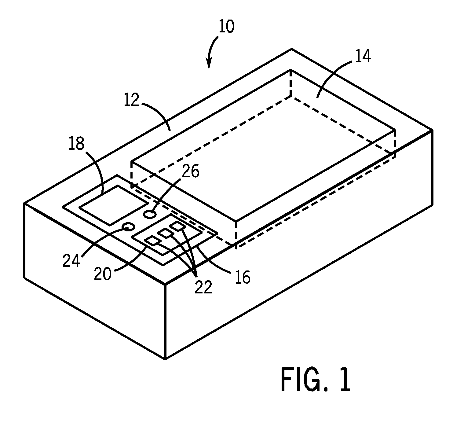
[0023]FIG. 1 illustrates an exemplary battery charger 10, which contains power supply circuitry in accordance with present embodiments. The battery charger 10 includes an outer housing 12 and a battery compartment 14 into which one or more batteries may be placed during a battery charging operation. An exemplary user interface 16 contains a display panel 18 through which the battery charger 10 may communicate information, such as charge status, to a user and a control panel 20 that may allow the user to manually input information regarding battery rating, type, and so forth. In the embodiment shown, the user may communicate this information via push buttons 22. In other embodiments, the means of conveying information about the battery could additionally be switches, keypads, and so forth. In yet other embodiments, information about the batteries, such as a type of battery, may be automatically detected. Further, in some embodiments, the battery charger 10 may contain one or more ind...


PUM


Abstract

A technique for dynamically adjusting an output voltage of forward converter circuits for a battery charging operation is provided. The technique allows for varying voltage at the charging battery by manipulating the duty cycles of two forward converter circuits. Method and systems allow for increasing synchronized duty cycles in a pair of forward converter circuits in response to a changing battery charge state that requires a higher voltage output then changing a phase shift between the duty cycles in response to further increases in output voltage demand. The methods and systems also allow for setting a phase shift between duty cycles in a pair of forward converter circuits based on battery rating and then altering pulse width in response to changing battery charge state.

Description

BACKGROUND[0001]The present disclosure relates generally to battery charging operations, and more particularly, to methods and systems for controlling a dual circuit inverter to dynamically adjust an output voltage of a battery charger.[0002]Power supply circuits typically convert AC power to an output suitable for battery charging operations. The output power is provided at an appropriate voltage or current level and may be controlled and regulated according to an algorithm or regime based on the requirements of the battery being charged. Battery chargers are often required to charge a range of battery sizes and types used in a variety of types of applications, such as automotive, industrial, household, and so forth. For instance, battery chargers may need to be equipped to handle a range of battery voltages (e.g. 6V, 12V, 24V, and so forth) and a variety of battery chemistries (e.g. lead acid, lithium ion, nickel cadmium, and so forth).[0003]The load requirements of the highest ra...

Claims


Application Information

Patent Timeline
Patent Type & Authority Patents(United States)
IPC IPC(8): H02J7/04H02M1/084H02M3/34H02M5/00
CPCH02J7/0081H02J7/045H02M3/33561H02M3/3376H02M2003/1586H02M3/3353H02J7/007184H02M3/1586
Inventor VOGEL, BERNARD J.
Owner ILLINOIS TOOL WORKS INC
Why Eureka
Try Eureka