Measurement of sliding friction-induced vibrations for biomimetic tactile sensing

a technology of biomimetic tactile sensing and vibration measurement, which is applied in the direction of distance measurement, instruments, and apparatus for force/torque/work measurement, etc., can solve the problems of preventing the development of next-generation robots for off-factory jobs, industrial robots lack the most tactile sensorial abilities of humans, and the lack of robots' generation of human ability to carry on delicate tasks, etc., to achieve wide dynamic range, wide dynamic range, and high detection sensitivity

Active Publication Date: 2012-05-22
UNIV OF SOUTHERN CALIFORNIA
View PDF147 Cites 22 Cited by
  • Summary
  • Abstract
  • Description
  • Claims
  • Application Information

AI Technical Summary

Benefits of technology

[0017]Embodiments of the present disclosure are directed to biomimetic sensors, and related structures and processes. Exemplary embodiments of the present disclosure include sensory devices that have features comparable to features found in biological systems. In particular, they may use biomimetic mechanical structures similar to those found in the finger tip to endow a set of simple, robust electronic sensors with a wide range of modalities and sensitivities similar to those found in biological mechanoreceptors. Exemplary sensory devices include a sensor assembly whose basic form and function are similar to that of a human finger tip. The sensory device may have a biomimetic shape of a core with covering skin and pulp (fluid reservoir) that results in distinctive and readily detectable patterns of impedance changes across an array of electrodes disposed on the core, to take advantage of the various distortions of the pulp produced by the contact parameters to be detected and discriminated. High detection sensitivity and wide dynamic range can be achieved for monitoring and / controlling the forces between a manipulator and objects being manipulated. The biomimetic designs of such sensor assemblies can allow for detection of stimulus features, e.g., by feature extraction circuitry, including those features that may be most useful for automatic adjustment of contact force to achieve and maintain stable and efficient grasp of an object. An exemplary embodiment comprises a device through which a set of information is generated concerning tactile interaction between a manipulator and an object to be manipulated and recognized. Such a device can be incorporated into autonomous robots, telerobots or prosthetic limbs. The tactile information may be generated either by robot or prosthetic finger tips.
[0018]Biomimetic tactile sensors taught herein may possess softness, elasticity, and some mechanical resistance that mimics natural human skin. Such sensors can detect and discriminate various aspects of contact with external objects, including the direction and magnitude of force, the location, extent and shape of the contacting object, and small movements associated with impending slip. Furthermore, such sensors may discriminate thermal properties of contacted objects through heat-flow sensing.
[0019]Exemplary embodiments may employ a number of small, local electrodes, e.g., deployed in a curved array, as part of a sensing modality having a shape and mechanical properties to mimic those of a biological finger tip. Such electrodes can be used to detect changes in impedance of a fluid within the sensor. Each sensing electrode may be energized to provide an independent measure of the local mechanical deformations of the overlying membrane based on its impedance with respect to a remote common electrode. Further improvements are described to enhance the sensitivity and dynamic range of each sensing electrode by contouring the inner surface of the overlying membrane. In further embodiments, neural networks may compute directly the actuator adjustments required to maintain stable grip of objects with a variety of shapes and force vectors in a manner similar to that employed by neural control of the human hand.

Problems solved by technology

Present generations of robots lack most of the tactile sensorial abilities of humans.
This limitation prevents industrial robots from being used to carry on delicate tasks of enormous practical relevance (such as assembly operations and handling of fragile objects) and, even more, it prevents the development of next-generation robots for off-factory jobs (agriculture, home, assistance to the disabled, etc.).
Due to limitations in currently available tactile sensing technology discussed below, currently available prosthetic fingers provide little or no sensing capabilities and cannot make use of these highly effective biological control strategies.
Unfortunately, while it would be desirable for the above-listed groups of tactile sensors to respond in much the same way that the human finger does, many of them can provide only limited information about contact with an object whose position, orientation and mechanical properties are highly predictable.
It is difficult to integrate these components into the tactile surfaces of manipulators, which are often required to have contoured, compliant surfaces to facilitate handling of various objects.
In order to achieve the requisite sensitivity, the individual sensors tend to be relatively fragile and subject to mechanical damage over the wide dynamic range of forces to which they may be exposed.
The large number of electrical connections between sensors and signal processing circuitry tend to be difficult and expensive to assemble, difficult to protect from environmental hazards such as water and grit, and difficult or impossible to repair if damaged.
For example, most micro-electromechanical system (“MEMS”) sensors provide good resolution and sensitivity, but lack the robustness for many applications outside the laboratory.
Sensing of friction-induced vibrations has been a particular challenge in the development of tactile sensors.
When this occurs, the power transferred into the skin by friction gives rise to acoustic vibrations in the skin and pulp of the finger.
Many attempts to develop a sensor capable of measuring such small vibrations have been made (Howe, Cutkosky, Dario), but they have required fragile dynamic sensors residing very close to the contact surface to achieve the needed sensitivity.
In this location fragile sensing devices are at a high risk for damage and experience short lifetimes and expensive repair costs.
Many tactile sensing arrays have been fabricated using MEMS but they are not suitable for mounting on such surfaces or for use in environments that include heavy loads, dust, fluids, sharp edges and wide temperature swings.
If skin-like elastic coverings are placed on top of sensor arrays, they generally desensitize the sensors and function as low-pass temporal and spatial filters with respect to incident stimuli, thereby attenuating dynamic information.
Neurophysiologists and psychologists often correlate the activity of somatosensory receptors and design measures of psychophysical percepts according to canonical physical parameters, but there is little evidence that the nervous system actually extracts direct representations of such parameters as an intermediate stage between sensation and performance.
In fact, information theory suggests that such an intermediate representation would add noise and reduce information content, which would place such a strategy at an evolutionary disadvantage.
It is difficult to apply to anthropomorphic robots and prosthetic limbs that can perform a broad and unpredictable range of tasks associated with activities of daily living.
The problem may further be complicated by environmental factors in such environments (e.g. temperature, moisture, sharp edges etc.), which tend to damage or bias sensitive and / or physically exposed transducers.
Furthermore, such sensors may discriminate thermal properties of contacted objects through heat-flow sensing.

Method used


Image

  • Measurement of sliding friction-induced vibrations for biomimetic tactile sensing
  • Measurement of sliding friction-induced vibrations for biomimetic tactile sensing
  • Measurement of sliding friction-induced vibrations for biomimetic tactile sensing

Examples


Embodiment Construction

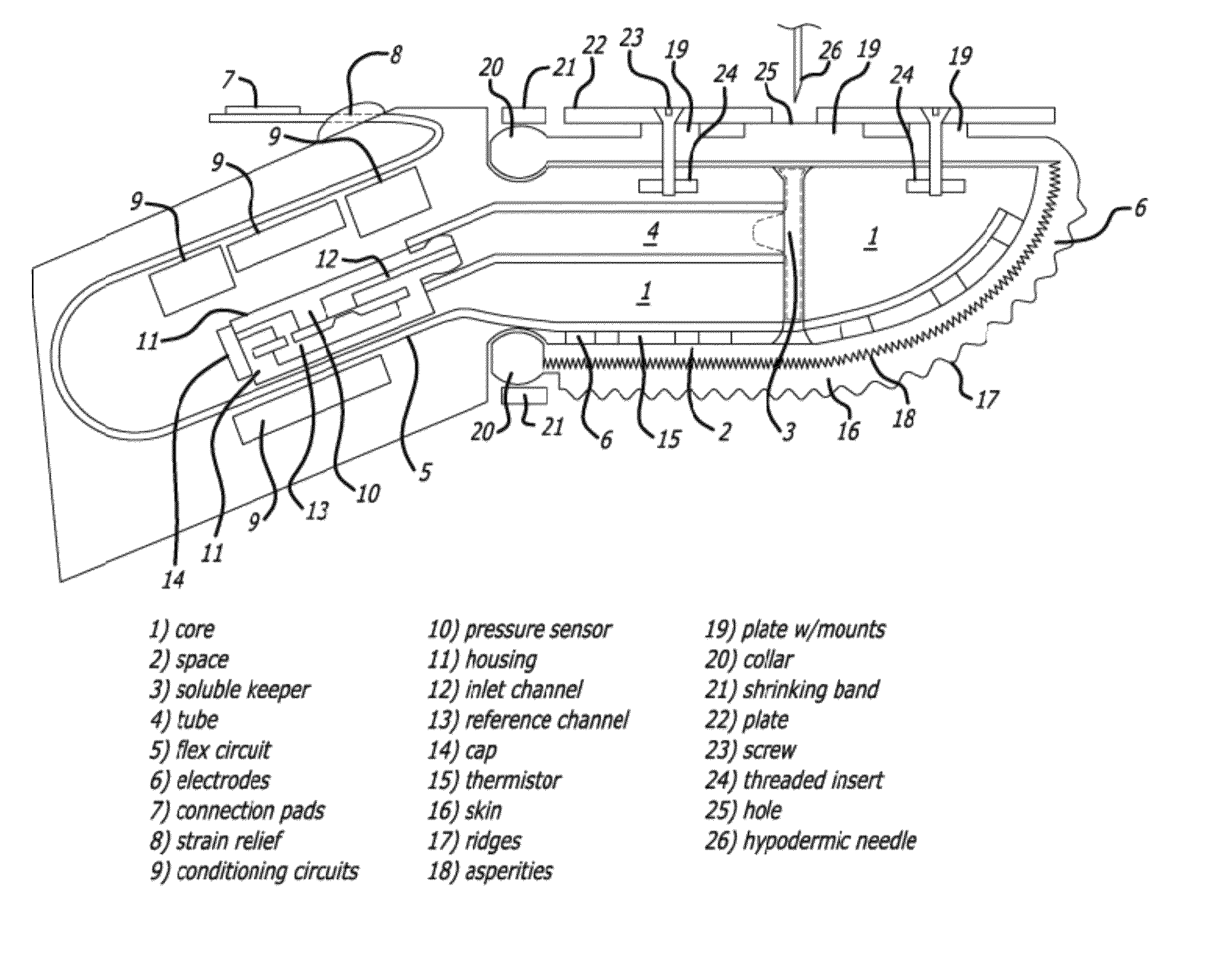
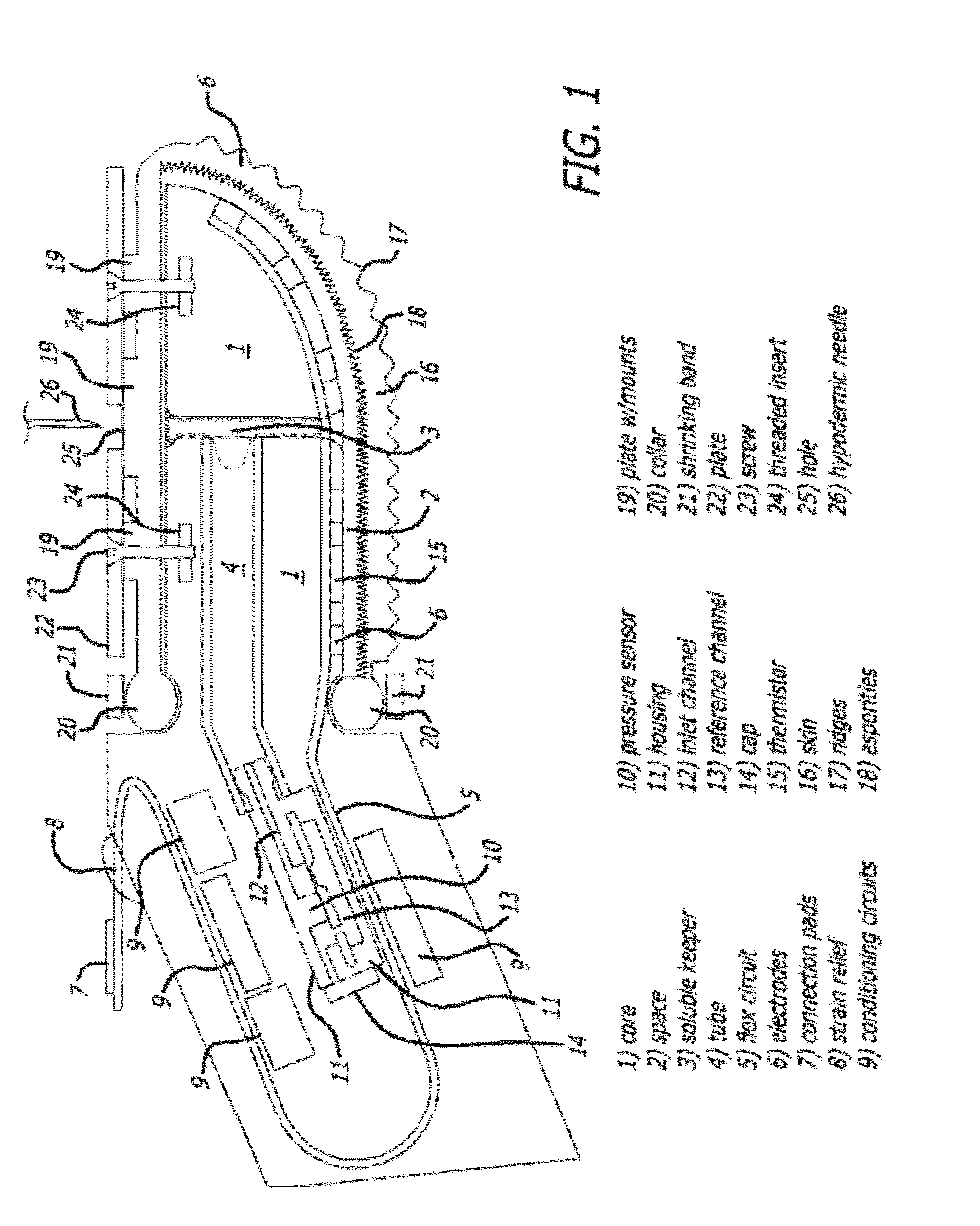
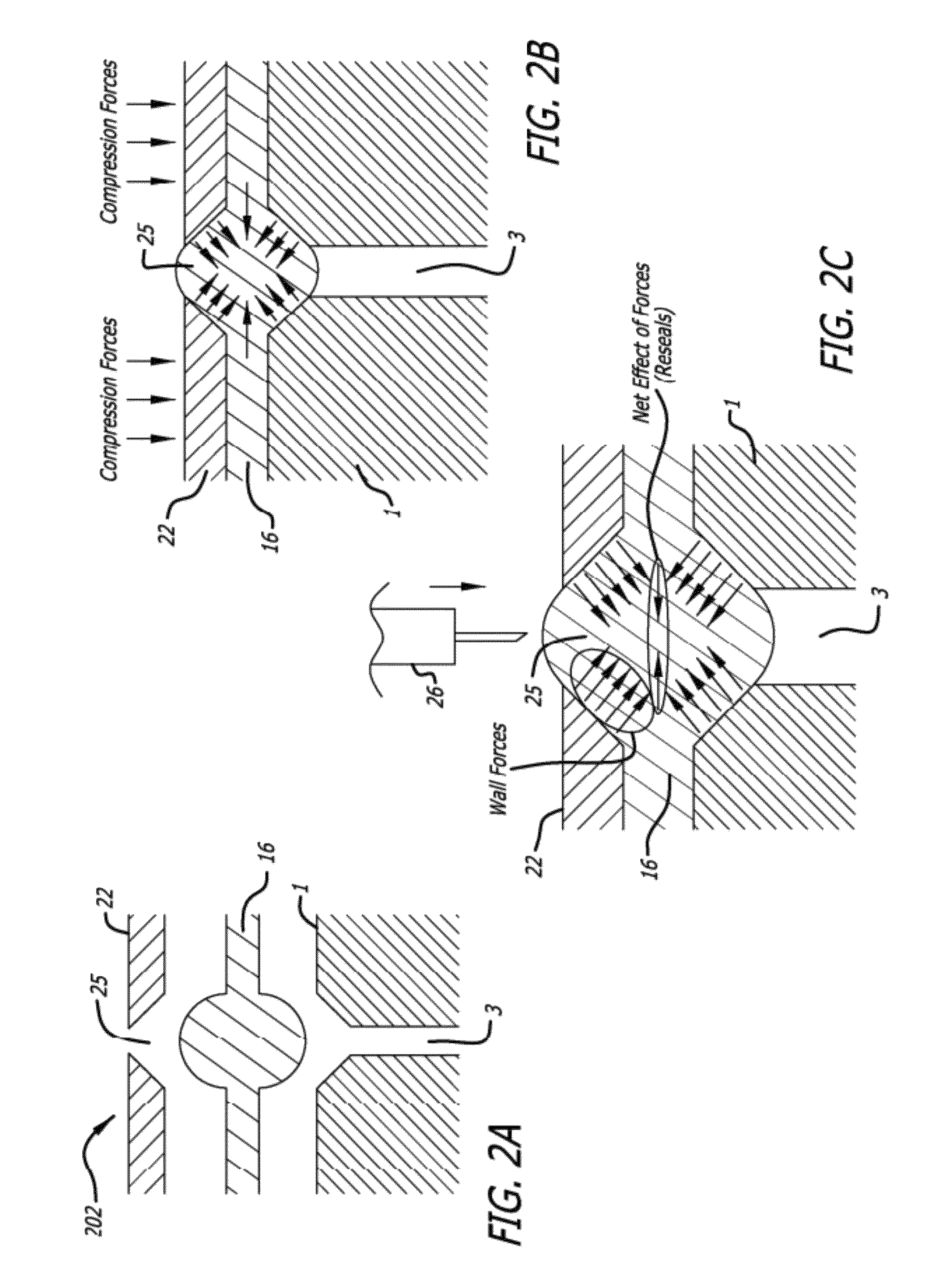
[0046]The detailed description set forth below is intended as a description of exemplary embodiments of the tactile sensory system and method and is not intended to represent the only embodiments in which the biomimetic tactile sensor systems and methods can be practiced. The term “exemplary” used throughout this description means “serving as an example, instance, or illustration,” and should not necessarily be construed as preferred or advantageous over other embodiments. The detailed description includes specific details for the purpose of providing a thorough understanding of the tactile sensory systems and methods. It will be apparent, however, to those skilled in the art that the tactile sensory systems and methods may be practiced without these specific details. In some instances, well-known structures and devices are shown in block diagram form in order to avoid obscuring the concepts of the tactile sensory systems and methods.

[0047]A prosthetic hand or anthropomorphic roboti...


PUM

PropertyMeasurementUnit
diameteraaaaaaaaaa
diameteraaaaaaaaaa
center frequencyaaaaaaaaaa

Abstract

Tactile sensors are disclosed that mimic the human fingertip and its touch receptors. The mechanical components are similar to a fingertip, with a rigid core surrounded by a weakly conductive fluid contained within an elastomeric skin. The deformable properties of the finger pad can be used as part of a transduction process. Multiple electrodes can be mounted on the surface of the rigid core and connected to impedance measuring circuitry within the core. External forces deform the fluid path around the electrodes, resulting in a distributed pattern of impedance changes containing information about those forces and the objects that applied them. Strategies are described for extracting features related to the mechanical inputs and using this information for reflexive grip control. Controlling grip force in a prosthetic having sensory feedback information is described. Pressure transducers can provide sensory feedback by measuring micro-vibrations due to sliding friction.

Description

CROSS-REFERENCE TO RELATED APPLICATIONS[0001]This application is a continuation-in-part of U.S. Patent application Ser. No. 11 / 692,718, filed 28 Mar. 2007 (now U.S. Pat. No. 7,658,119 B2, issued Feb. 9, 2010), and entitled “Biomimetic Tactile Sensor,” which claims priority to U.S. Provisional Patent Application No. 60 / 786,607, filed 28 Mar. 2006 and entitled “Biomimetic Tactile Sensor”; the entire contents of both of which applications are incorporated herein by reference. This application is also a continuation-in-part of U.S. Patent application Ser. No. 12 / 122,569, filed 16 May 2008 (now U.S. Pat. No. 7,878,075 B2, issued Feb. 1, 2011, and entitled “Biomimetic Tactile Sensor for Control of Grip,” which claims priority to U.S. Provisional Patent Application No. 60 / 939,009, filed 18 May 2007, and entitled “Biomimetic Tactile Sensor for Control of Grip”; the entire contents of both of which applications are incorporated herein by reference. This application also claims the benefit of...

Claims


Application Information

Patent Timeline
Patent Type & Authority Patents(United States)
IPC IPC(8): G01L1/10G01L7/08G01L1/02G01L11/04
CPCG01L5/228
Inventor LOEB, GERALD E.FISHEL, JEREMYWETTELS, NICHOLASSANTOS, VERONICA J.PECK, RAYMOND
Owner UNIV OF SOUTHERN CALIFORNIA
Why Eureka
Try Eureka