Platform telescoping mechanism

a platform and telescopic technology, applied in the direction of scaffolds, suspension devices, machine supports, etc., can solve the problems of fine adjustment, difficulty for hospital staff to manipulate imaging instruments, hospital personnel and imaging instruments or other medical equipment,

Active Publication Date: 2012-05-22
SHENZHEN MINDRAY BIO MEDICAL ELECTRONICS CO LTD
View PDF23 Cites 1 Cited by
  • Summary
  • Abstract
  • Description
  • Claims
  • Application Information

AI Technical Summary

Benefits of technology

[0005]An object of various embodiments of the invention is to overcome the disadvantages found in the prior art by providing a platform telescoping apparatus which occupies a smaller foot print than similar conventional systems and offers at least two degree of freedom to adjust the position of the platform.
[0018]In various embodiments, the second supporting arm is able to telescoping in a first direction with respect to the first supporting arm. In some embodiments after the patient's position has been adjusted by hospital personnel, the second supporting arm may then extend or retract substantially along the direction of the first supporting or the second supporting arm. After imaging, the platform, in some embodiments, retracts in a substantially horizontal direction so as to save or conserve the space occupied by the imaging system. For example, when a patient is about to receive chest x-ray, the platform may be configured to be in an upright position, and the first supporting arm may be configured to be in a retracted position.

Problems solved by technology

However, longer supporting arms inevitably occupy larger space and often causes difficulty for hospital staff to manipulate the imaging instrument and / or adjust or fine tune the patient's position for better imaging.
Longer supporting arms may also cause hospital personnel and the imaging instrument or other medical equipment to compete for the limited space.
This is especially true when considering that the target locations on different patients, even for the same diagnostic purpose, are generally different such that fine adjustment may be necessary and may often be difficult for an imaging system with a short supporting arm.

Method used


Image

  • Platform telescoping mechanism
  • Platform telescoping mechanism
  • Platform telescoping mechanism

Examples


Embodiment Construction

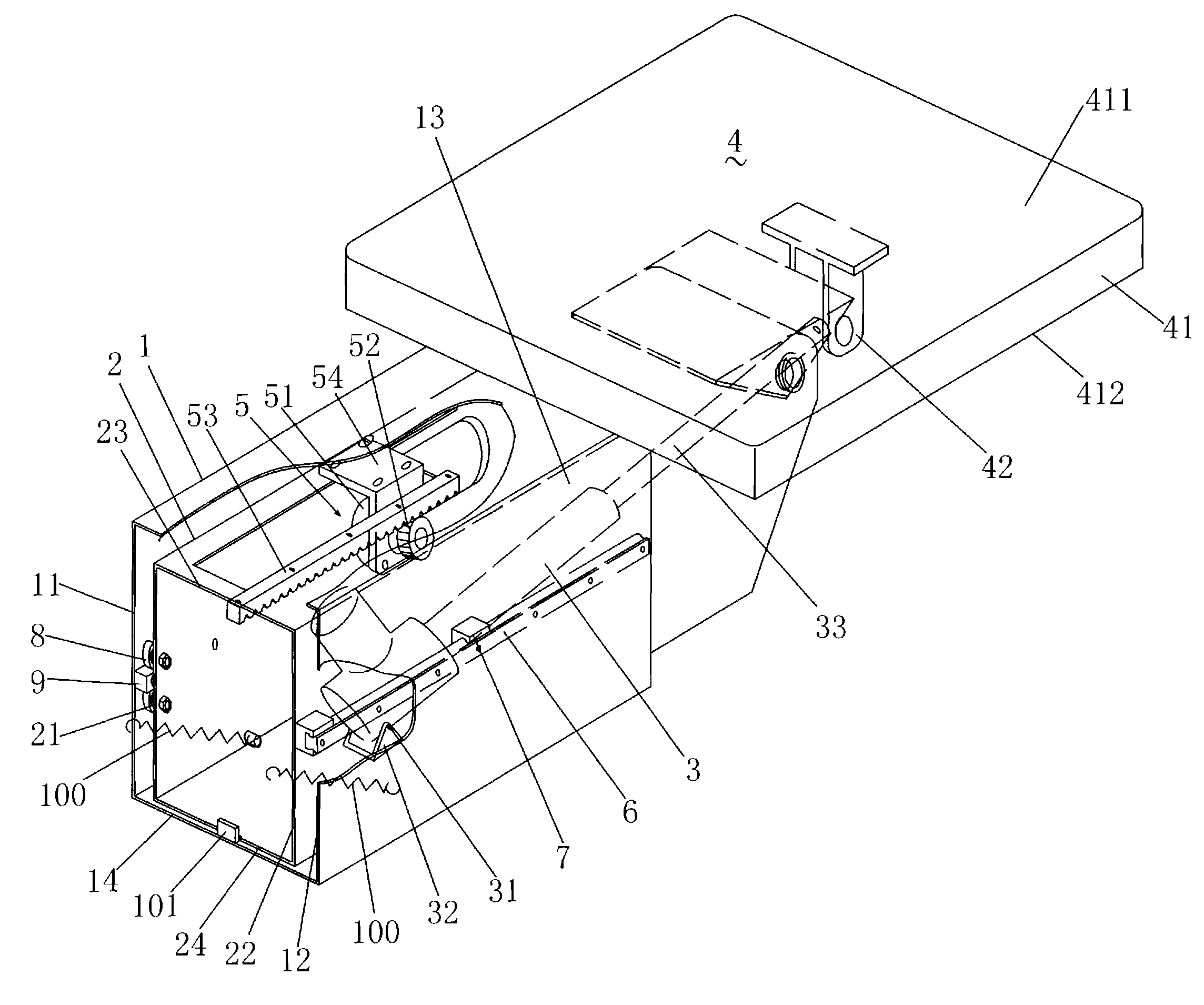
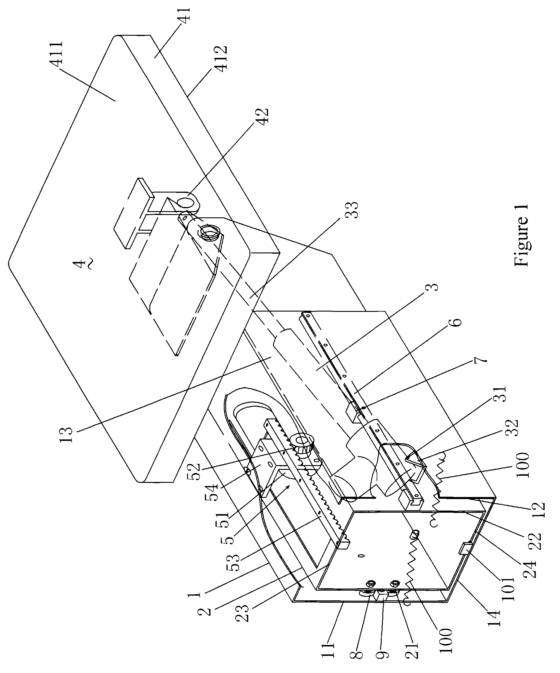
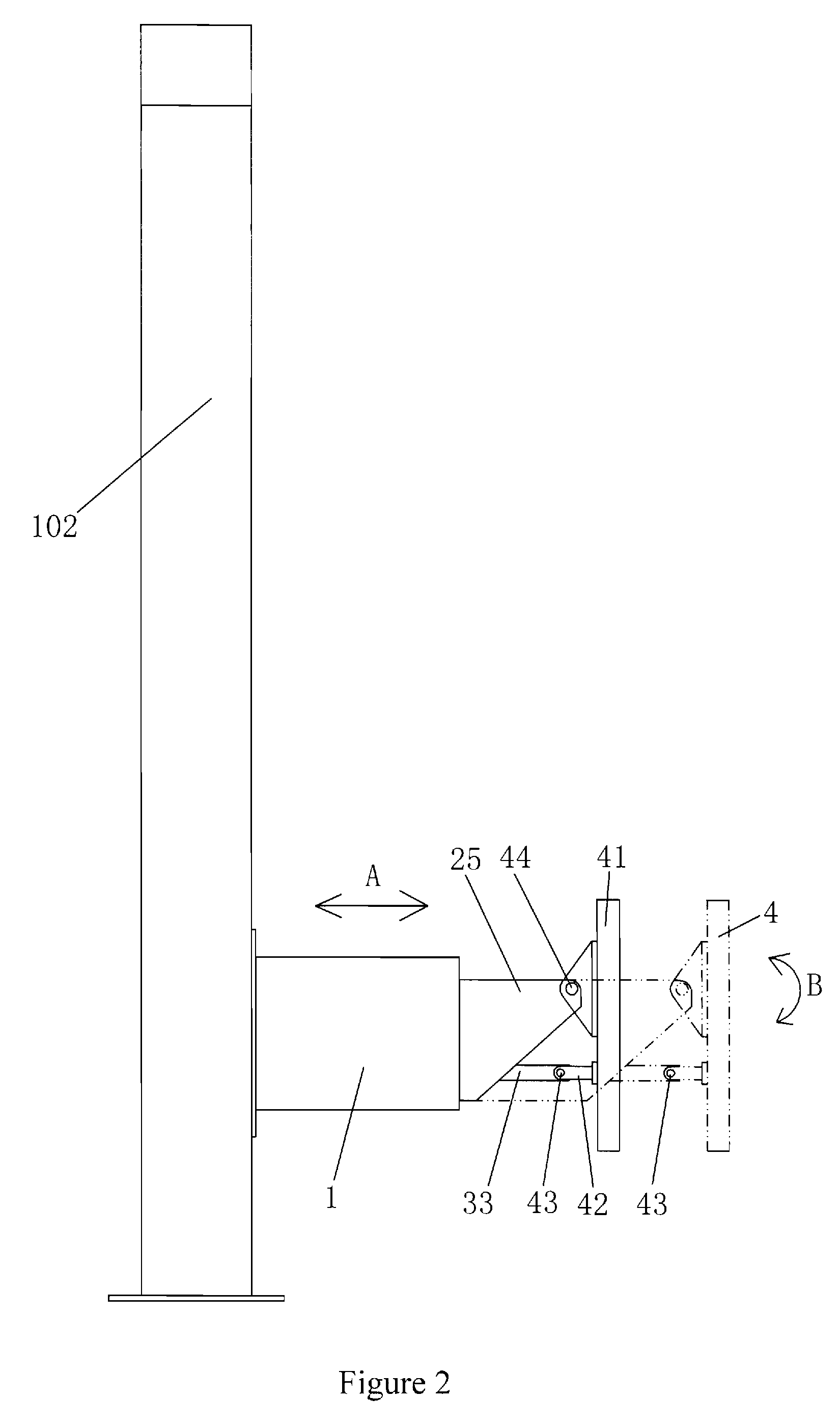
[0028]As shown in FIGS. 1 to 7, a platform telescoping mechanism according to various embodiments comprises a platform 4, a first supporting arm 1, a second supporting arm 2, a telescopic driving mechanism 5 comprising a first power output end, and a rotational driving mechanism 3 comprising a second power output end. The platform 4 and the second supporting arm 2 are rotatably or pivotally connected or attached to or otherwise integrated with each other by using a respective rotational or pivotable joint, and the first supporting arm 1 and the second supporting arm 2 are coupled with each other along a linear direction by using a translational joint. In some embodiments, the telescopic driving mechanism 5 may be attached or connected to or otherwise integrated with the first supporting arm 1 and comprises a first power output end which is connected to the second supporting arm 2 and drives the second supporting arm 2 to move in a first direction. In some embodiments, the rotational...


PUM


Abstract

Disclosed are various embodiments of a platform telescoping system which comprises a platform, a first supporting arm, a second supporting arm, a telescopic driving mechanism which comprises a first power output, end and a rotational driving mechanism which comprises a second power output end. The first power output end is integrated with the second supporting arm and causes the second supporting arm to move in a first direction, and the second power output end is integrated with the platform and causes the platform to pivot between a first position and a second position. The second supporting arm telescopes with respect to the first supporting arm for adjusting the position of the platform. The space occupied by the platform telescoping system may be reduced while its functions enhanced.

Description

CROSS-REFERENCE TO RELATED APPLICATION[0001]This application claims the benefit of Chinese Patent Application No. 200810066173.8 which is filed on Mar. 24, 2008 into State Intellectual Property Office of the People's Republic of China.FIELD OF INVENTION[0002]The present invention relates to a platform telescoping mechanism.BACKGROUND ART[0003]A cantilevered X-ray digital camera system generally comprises a platform which is mounted on a carriage. The carriage may be attached to an upright column by using a supporting arm or other structural members. The platform may be driven by or move along with the carriage along the upright column to move up and down. Meanwhile, the platform may be able to rotate around the supporting arm by a certain angle. X-ray photographing of various target locations on patients may be benefited by the capability of the platform to move up and down and to rotate about one or more certain axes.[0004]The supporting arm in these x-ray imaging systems generally...

Claims


Application Information

Patent Timeline
Patent Type & Authority Patents(United States)
IPC IPC(8): F16M11/00E04G1/00
CPCA61B6/0457A61B6/0487
Inventor SHI, ZHIYUANCHEN, XIAOHONG
Owner SHENZHEN MINDRAY BIO MEDICAL ELECTRONICS CO LTD
Why Eureka
Try Eureka