
Overtube and endoscope system suitable for treatment such as submucosal dissection

Active Publication Date: 2012-05-29
OLYMPUS CORP
View PDF18 Cites 1 Cited by
  • Summary
  • Abstract
  • Description
  • Claims
  • Application Information

AI Technical Summary

Benefits of technology

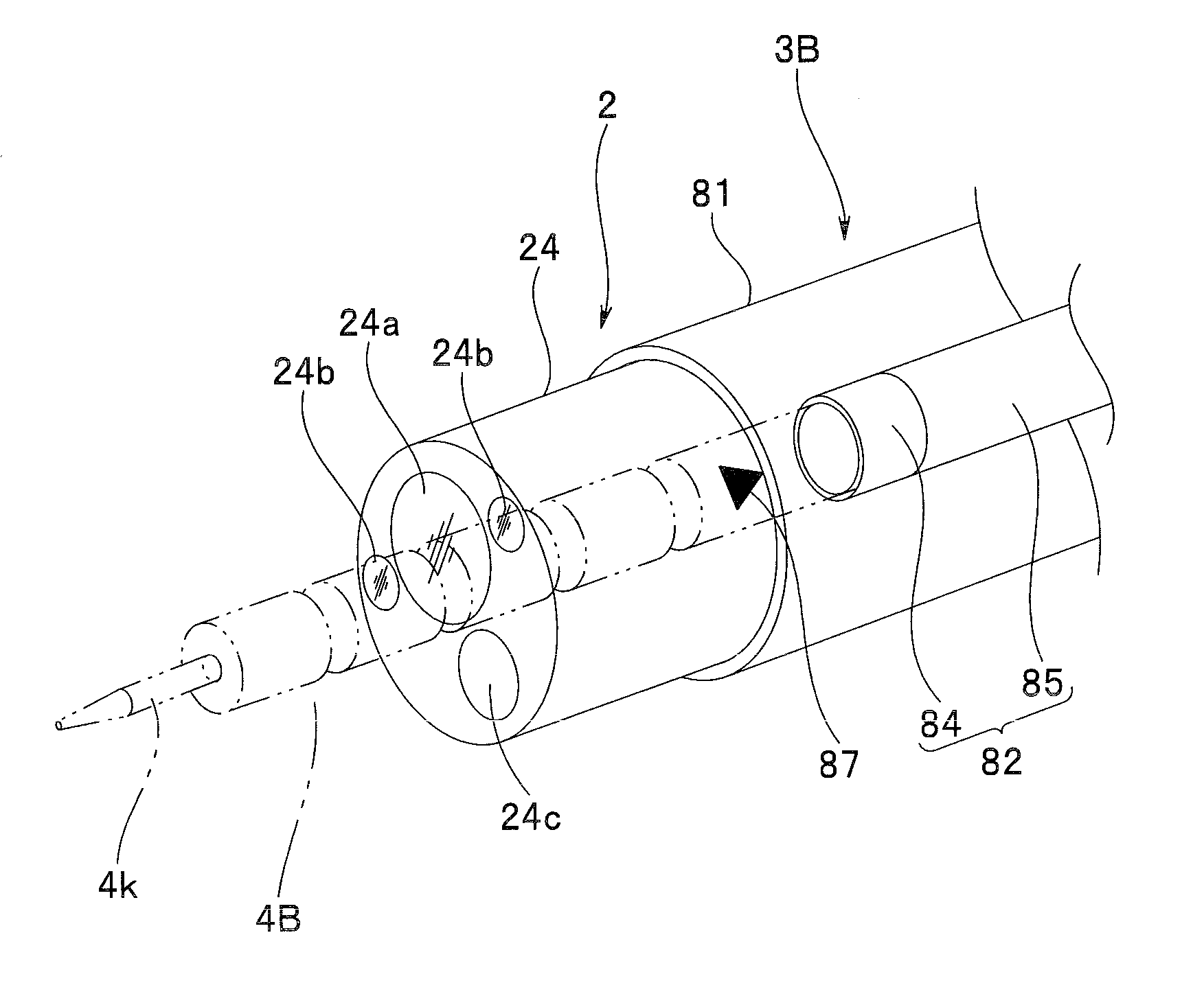
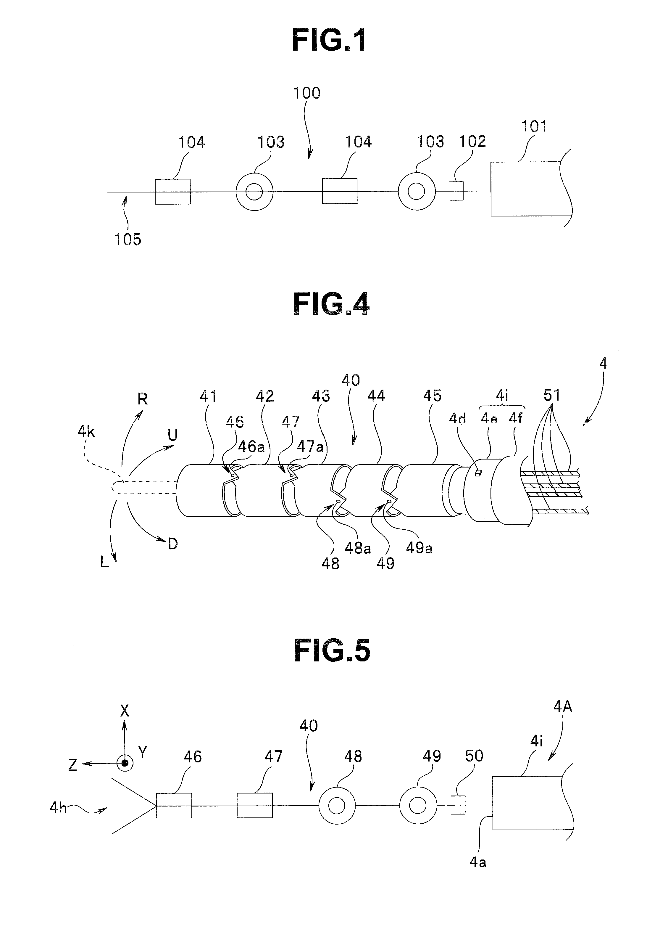
The present invention provides an overtube for an endoscope system that includes an endoscope insertion portion and a manipulator insertion portion. The overtube has a distal end surface with an endoscope protrusion amount determination portion and an observation optical system observation direction determination portion. The manipulator insertion portion has a driving portion with a plurality of joint pieces connected on a distal end side, and the joint pieces are configured as a first joint rotating clockwise and counterclockwise around a first shaft and a second joint rotating clockwise and counterclockwise around a second shaft perpendicular to the first shaft. The overtube also has at least one manipulator passing hole through which the manipulator insertion portion passes. The endoscope protrusion amount determination portion determines the length of the endoscope insertion portion protruding from the distal end surface of the overtube, and the observation optical system observation direction determination portion determines the vertical and lateral observation directions of the observation optical system. The joint driving direction determination portion determines the first shaft of the first joint and the second shaft of the second joint in an observation direction of the observation optical system. The technical effect of this invention is to provide a more efficient and precise overtube for an endoscope system that allows for better visualization and manipulation of the endoscope.

Problems solved by technology

If the operator insufficiently grasps the situation, an operation of the active joint may bring the knife arm or the joint into contact with a body wall or the like.

Method used


Image

  • Overtube and endoscope system suitable for treatment such as submucosal dissection
  • Overtube and endoscope system suitable for treatment such as submucosal dissection
  • Overtube and endoscope system suitable for treatment such as submucosal dissection

Examples


Embodiment Construction

[0036]Now, an embodiment of the present invention will be described with reference to the drawings.

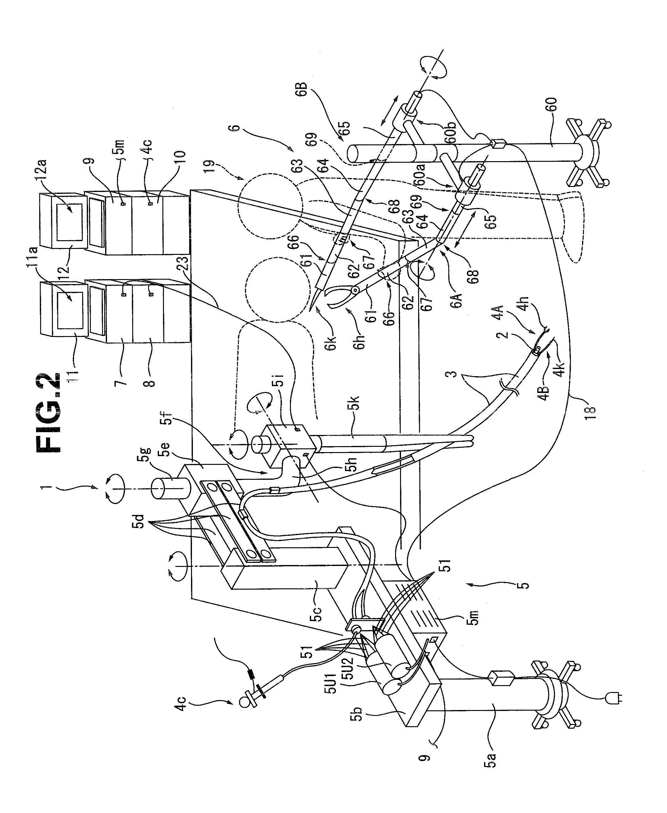
[0037]As shown in FIG. 2, an endoscope system 1 includes an electronic endoscope (hereinafter simply referred to as an endoscope) 2, an overtube 3, a plurality of manipulator apparatuses 4 (a grasping manipulator 4A and a high frequency manipulator 4B described later in the present embodiment), a support base 5, a manipulator operation apparatus 6, an endoscope light source apparatus 7, a video processor 8, a control device 9, a high frequency power supply apparatus 10, and display apparatuses 11 and 12.

[0038]The support base 5 includes a column 5a. A table 5b is secured to the column 5a. A vertical arm 5c stands on an upper surface of the table 5b. The vertical arm 5c is mounted to the table 5b rotatably clockwise and counterclockwise. A first arm holding member 5e is provided on the vertical arm 5c, for example, via a plurality of securing members 5d. Reference numeral 5f denotes an ...


PUM


Abstract

An overtube includes: an endoscope insertion portion passing hole through which an insertion portion of an endoscope is passed; and at least one manipulator passing hole through which a manipulator insertion portion of a manipulator apparatus is passed. The manipulator insertion portion includes a driving portion which has at least one first joint and one second joint rotating clockwise and counterclockwise. The endoscope insertion portion passing hole includes an endoscope protrusion amount determination portion which determines a length of a protrusion of the endoscope; and an observation optical system observation direction determination portion which determines an observation direction of the endoscope. The manipulator passing hole includes a manipulator protrusion amount determination portion which determines positions of the first joint of the manipulator within the observation optical system; and a joint driving direction determination portion which determines rotating directions of shafts of joints within the observation direction.

Description

[0001]This Application claims benefit of Japanese Application No. 2008-119893 filed in Japan on May 1, 2008, the contents of which are incorporated by this reference.BACKGROUND OF THE INVENTION[0002]1. Field of the Invention[0003]The present invention relates to an overtube and an endoscope system for performing treatment such as submucosal dissection using a manipulator apparatus under observation by an endoscope.[0004]2. Description of the Related Art[0005]In recent years, procedures have been performed such as endoscopic mucosal resection (EMR) or endoscopic submucosal dissection (ESD) of providing a plurality of treatment instrument channels in an insertion portion of an endoscope, introducing treatment instruments such as a grasping device and an IT knife into a body through the respective treatment instrument channels to resect a lesion in mucosal tissue in the body. Clinicians who preform the procedures need good skills.[0006]In recent years, various manipulators including an...

Claims


Application Information

Patent Timeline
Patent Type & Authority Patents(United States)
IPC IPC(8): A61B1/00
CPCA61B1/018A61B1/00149
Inventor NAITO, KIMIHIKO
Owner OLYMPUS CORP
Learn More