Power management unit with battery detection controller and switchable regulator block

a technology of power management unit and regulator block, which is applied in the direction of d transporting and packaging, ac network circuit arrangement, etc., can solve the problems of electronic device turning off, undesirable on/off cycle repeating, voltage regulator in pmu,

Active Publication Date: 2012-05-29
AVAGO TECH INT SALES PTE LTD
View PDF8 Cites 26 Cited by
  • Summary
  • Abstract
  • Description
  • Claims
  • Application Information

AI Technical Summary

Problems solved by technology

However, if the current drawn by the electronic device exceeds the limited charging current provided by the PMU battery charger, the voltage across the capacitor will drop below the threshold voltage, thereby causing voltage regulators in the PMU and, consequently, the electronic device to turn off.
The undesirable on / off cycles can continue to repeat as long as a battery is not installed in the electronic device and the charger input of the conventional PMU is connected to an external power source.
Among other problems, the undesirable on / off cycles can degrade a user's experience using the electronic device.

Method used


Image

  • Power management unit with battery detection controller and switchable regulator block
  • Power management unit with battery detection controller and switchable regulator block
  • Power management unit with battery detection controller and switchable regulator block

Examples


Embodiment Construction

[0014]The present invention is directed to a power management unit with battery detection. The following description contains specific information pertaining to the implementation of the present invention. One skilled in the art will recognize that the present invention may be implemented in a manner different from that specifically discussed in the present application. Moreover, some of the specific details of the invention are not discussed in order not to obscure the invention.

[0015]The drawings in the present application and their accompanying detailed description are directed to merely exemplary embodiments of the invention. To maintain brevity, other embodiments of the present invention are not specifically described in the present application and are not specifically illustrated by the present drawings.

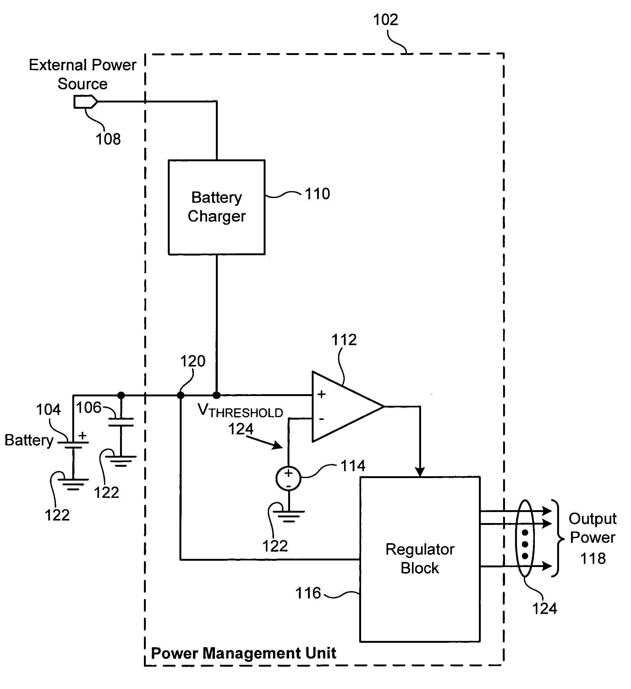
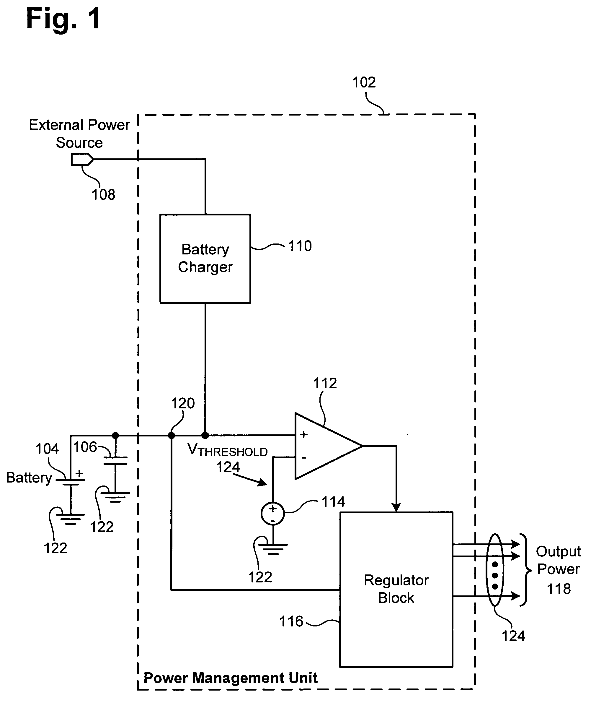
[0016]FIG. 1 shows a block diagram of conventional PMU 102 coupled to a battery, a capacitor, and an external power source. Conventional PMU 102, which is coupled to battery 10...


PUM


Abstract

According to one exemplary embodiment, a power management unit residing in an electronic device includes a battery detection controller coupled to a battery charger and a regulator block, where the regulator block is capable of providing power to the electronic device. The battery detection controller is configured to turn off the regulator block when the battery charger is coupled to an external power source and is not coupled to a battery of the electronic device. The battery detection controller can be further configured to turn on the regulator block when the battery charger is coupled to the external power source and is coupled to the battery if the battery has a battery voltage greater than a threshold voltage.

Description

[0001]The present application claims the benefit of and priority to a pending provisional patent application entitled “Battery Detection Circuit and Method,” Ser. No. 60 / 901,836 filed on Feb. 16, 2007. The disclosure in that pending provisional application is hereby incorporated fully by reference into the present application.BACKGROUND OF THE INVENTION[0002]1. Field of the Invention[0003]The present invention generally relates to the field of electrical circuits and systems. More particularly, the invention relates to circuits and systems utilizing a battery and / or a battery charger.[0004]2. Background Art[0005]A battery-powered electronic device, such as a cellular phone, a laptop computer, or an MP3 player, typically includes a power management unit (PMU) coupled to a battery. The PMU can include a battery charger and a number of voltage regulators for providing regulated power to the electrical circuits in the electronic device. In a conventional PMU, as soon as an external powe...

Claims


Application Information

Patent Timeline
Patent Type & Authority Patents(United States)
IPC IPC(8): H02J7/00
CPCH02J7/0068
Inventor YANG, KEN GUO CHI
Owner AVAGO TECH INT SALES PTE LTD
Why Eureka
Try Eureka