Stationary remote control transmitter

a transmitter and remote control technology, applied in the direction of electric programme control, electric controller, television system, etc., can solve the problems of limited longitudinal length of the case, inoperable limited operation of the rotation operation of the jog dial, etc., and achieve the effect of large outer diameter of the operation member

Inactive Publication Date: 2012-05-29
SMK CORP
View PDF9 Cites 85 Cited by
  • Summary
  • Abstract
  • Description
  • Claims
  • Application Information

AI Technical Summary

Benefits of technology

[0012]Due to a stationary-type with the bottom plane of the case as the placement plane, it is not necessary to consider the rotation operation by holding the case with hand for determining the size of the operation member, thus its diameter can be set to a large size that allows rotation operation in fine angular steps.
[0026]Further, although it is a stationary-type remote control transmitter, the rotation operation of the rotation operation plane of the operation member can be easily performed.

Problems solved by technology

However, since the remote control transmitter referred in JP '508 needs to transmit infrared control signals by aiming at controlled devices, the longitudinal length of the case is limited to dimensions that can be handled by a single hand, and the installed position and the size of the jog dial are set in such a way that the rotation operation of the jog dial installed on the plane is operable with the thumb of the hand that holds the case.
As a result, the size of the jog dial is smaller than the width of the case and the outer diameter of the jog dial also needs to be small so that the rotation operation is possible with the tip of a finger of the holding hand, therefore, there is a problem in operation of the rotation operation of the jog dial in fine angular steps.
However, same as the conventional transmitters, for the jog dial having the rotation operation plane that is parallel to the plane of the case, depending on the position relationship between an operator and the remote control transmitter, the elbow of the operator may be raised and the rotation operation is performed by touching it with a finger tip that is pointed in the vertical position, therefore there is a different problem in the operation.
On the other hand, if the rotation operation plane of the jog dial is formed along the vertical plane, the operation force for the rotation operation acts parallel to the placement plane of the case, thus the rotation operation may not be operable because the rotation operation plane is separated from the finger tip due to sliding of the case.
For the reasons described above, although the jog dial is suitable as an input means by rotation operation, it has not been used in stationary-type transmitters and its use has been limited in the remote control transmitters that are operated by holding the case with hand.

Method used


Image

  • Stationary remote control transmitter
  • Stationary remote control transmitter
  • Stationary remote control transmitter

Examples


Embodiment Construction

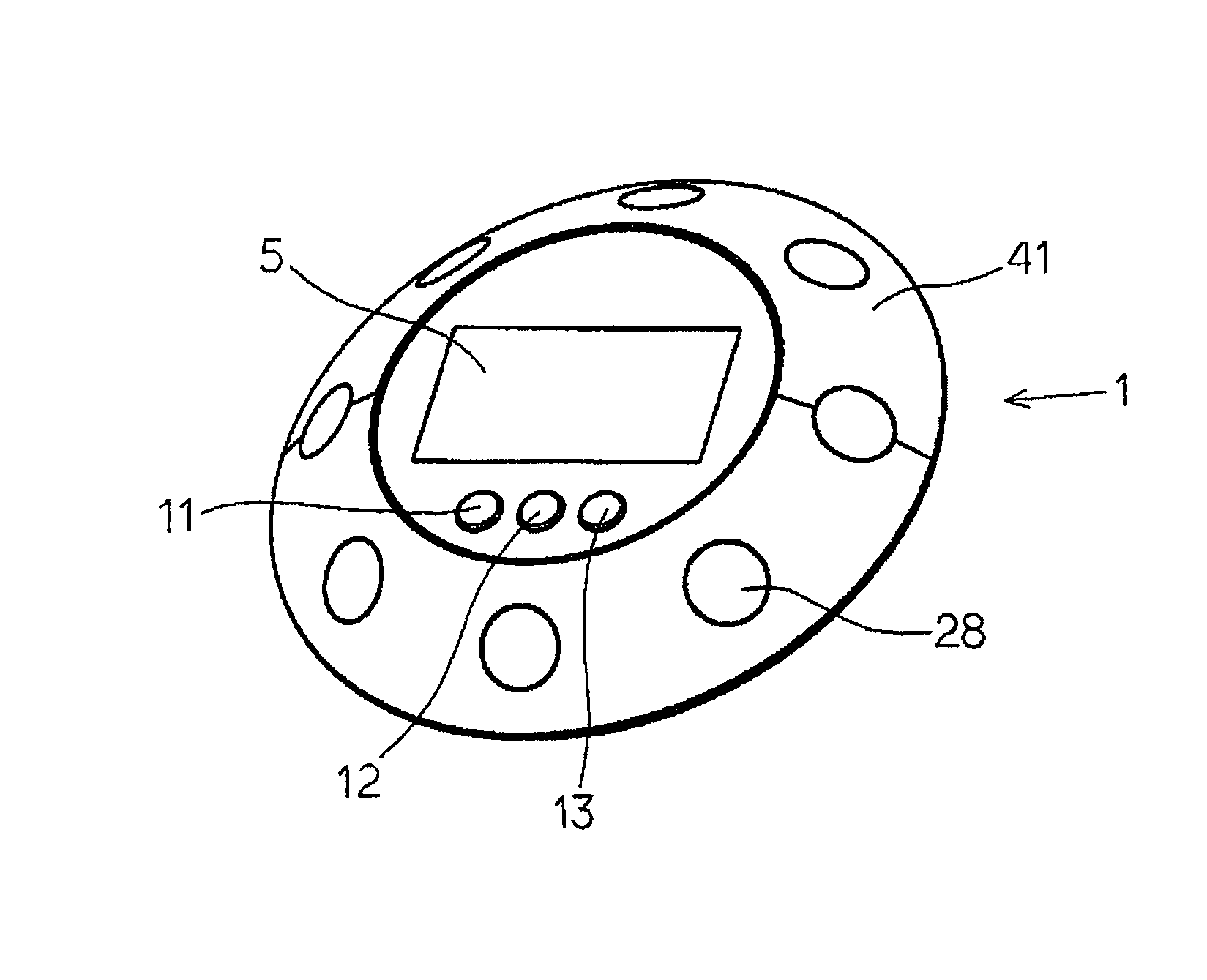
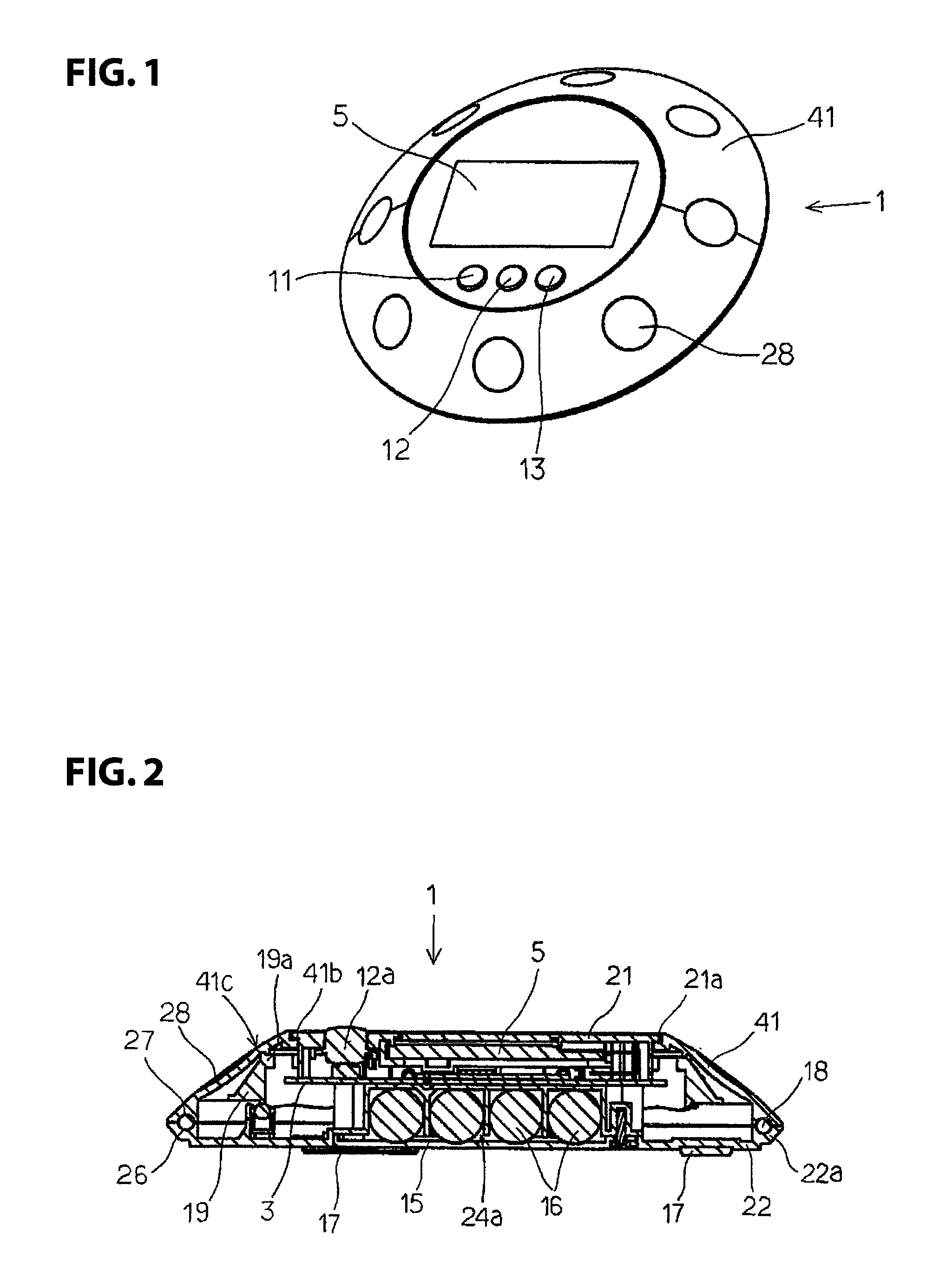
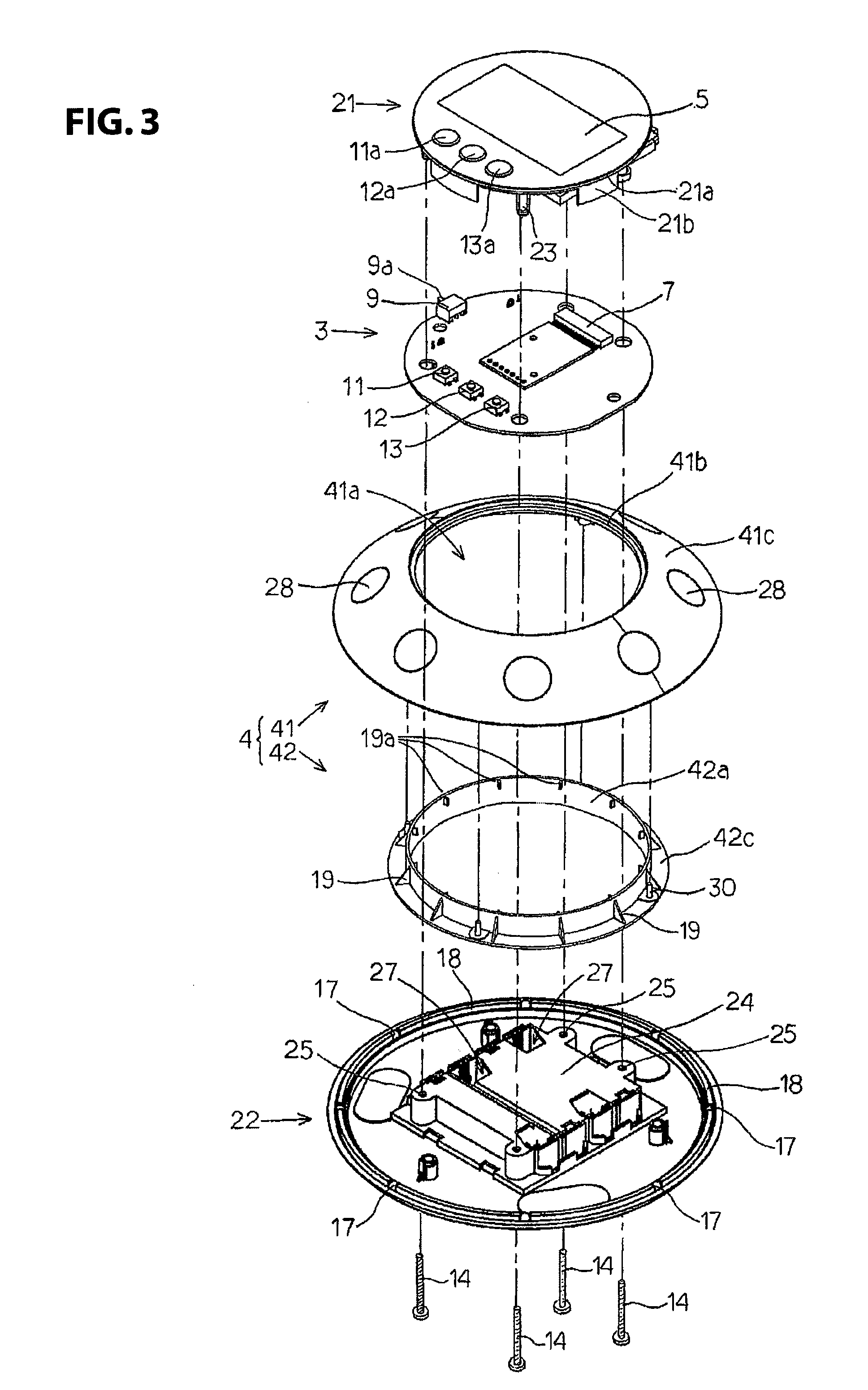
[0040]In the following, an embodiment of the stationary remote control transmitter 1 of the invention is explained using FIG. 1 to FIG. 6. FIG. 1 is a perspective view of the stationary remote control transmitter 1; FIG. 2 is a longitudinal cross-sectional view of the stationary remote control transmitter 1; FIG. 3 is an exploded perspective view seen from above the stationary-type remote control transmitter 1; FIG. 4 is an exploded perspective view seen from below and FIG. 5 is a main part enlarged prospective view showing the ring guide element of the large diameter disk member 22.

[0041]As shown in FIG. 3 and FIG. 4, the stationary remote control transmitter 1 includes an insulator case 2 that consists of the small diameter disk member 21 and the large diameter disk member 22, the circular printed circuit board 3 installed between the small diameter disk member 21 and the large diameter disk member 22, the ring-shaped operation member 4 that consists of the ring-shaped jog dial 41...


PUM


Abstract

The rotation operation plane of the ring-shaped operation members that operate the rotation is inclined with respect to the horizontal plane so that the rotation operation of the ring-shaped operation member can be performed without holding a finger in the vertical direction. Furthermore, since the rotation operation plane is inclined with respect to the placement plane of the case, static friction on the placement plane is generated by a force component of the operation force acting on the rotation operation plane and is perpendicular to the placement plane, thus the case does not move toward the rotation operation direction during the rotation operation.

Description

CROSS REFERENCE TO RELATED APPLICATION[0001]This application claims priority under 35 U.S.C. §119 to Japanese Patent Application No. 2008-224127 filed Sep. 1, 2008. The contents of that application, in their entirety, are incorporated herein by reference.TECHNICAL FIELD[0002]The present invention relates to a stationary remote control transmitter that controls controlled devices by transmitting control data, and more specifically to controlling of the controlled devices by rotation operations of a ring-shaped operation member.BACKGROUND OF THE INVENTION[0003]Normally, a remote control transmitter that controls Frame Advance, Play and Fast Play of recording in DVD recorders by installing a ring-shaped operation member called the jog dial that freely rotates on a case and by rotating a dial key is known as the remote control transmitter for remotely controlling image playing devices such as DVD recorders (See, Japanese Unexamined Patent Application Publication No. 2007-36508 (“JP '508...

Claims


Application Information

Patent Timeline
Patent Type & Authority Patents(United States)
IPC IPC(8): G05B19/02H04N5/00H04Q9/00
CPCG08C17/02H01H9/0235H01H19/005
Inventor OTSUKA, KENJINOGUCHI, RYUHEIMIYATA, NORIAKI
Owner SMK CORP
Why Eureka
Try Eureka