Relay

a relay and high-voltage technology, applied in the field of relays, can solve the problems of increasing cost, reducing the useful service life of the relay, and increasing the risk of continuously supplying current to the load circuit, so as to achieve no degradation of the performance of the relay and long useful service life

Active Publication Date: 2012-06-05
FUJITSU COMPONENENT LTD
View PDF15 Cites 33 Cited by
  • Summary
  • Abstract
  • Description
  • Claims
  • Application Information

AI Technical Summary

Benefits of technology

[0020]Further, since the arcs generated in the first gap and the second gap are both blown off outward and extinguished, it is possible to prevent the first opening and closing part and the second opening and closing part from being damaged. As a result, there is no degradation of the performance of the relay even after multiple opening and closing operations, so that the relay enjoys a long useful service life.
[0021]Further, there is no need to cross circuit interconnections formed on a printed circuit board on which the relay is mounted. Accordingly, it is possible to form circuit connections using only one side of the printed circuit board.

Problems solved by technology

In the case of applying a relay to such circuits, when the paired contacts of the relay in contact with each other are separated from each other, an arc current flows between the contacts because of the action of a high voltage on the relay, and this arc current damages the contacts so as to reduce the useful service life of the relay.
This is a problem in terms of reliability and also increases cost.
Therefore, even when the two contact pairs of the relay are open, the negative terminal of the direct-current power supply and the load circuit remain connected, so that the direct-current power supply and the load circuit are not completely independent of each other.
As a result, there is the risk of continuously supplying current to the load circuit particularly when the ground potential is unstable.
Further, the above-mentioned relay is not so configured as to be mountable on a printed circuit board.

Method used


Image

  • Relay
  • Relay
  • Relay

Examples


second embodiment

[0107]FIGS. 8A through 8C are an X2-side cut-away view, a Y2-side cut-away view, and a bottom (Z2-side) plan view, respectively, of a relay 10B according to the present invention.

[0108]The relay 10B includes two relay main bodies 130X1 and 130X2 incorporated and arranged side by side in the X1-X2 directions in a case 110B. Each of the relay main bodies 130X1 and 130X2 has the same configuration as a relay main body 130 shown in FIG. 9.

[0109]The case 110B includes a relay main body housing part 115X1 for housing the relay main body 130X1 and a relay main body housing part 115X2 for housing the relay main body 130X2. The relay main body housing parts 115X1 and 115X2 are formed side by side in the X1-X2 directions. The first and second permanent magnet pieces 30 and 40 are fixed to a top plate part 111B2 of the relay main body housing part 115X2 and a top plate part 111B1 of the relay main body housing part 115X1, respectively.

[0110]Referring to FIG. 9, the relay main body 130 includes...

first embodiment

[0115]The relay 10B operates with the relay main body 130X1 and the relay main body 130X2 operating simultaneously. The arcs generated in the gaps 17B and 27B during the operation of the relay 10B are both deflected outward and blown off toward a side plate part 112B and a side plate part 113B, respectively, so as to be immediately extinguished the same as in the case of the above-described relay 10A of the Therefore, the movable contact (corresponding to the movable contact 14C of FIG. 9) and the fixed contact (corresponding to the fixed contact 12C of FIG. 9) of each of the relay main bodies 130X1 and 130X2 are prevented from being damaged, so that the relay 10B has a long useful service life.

third embodiment

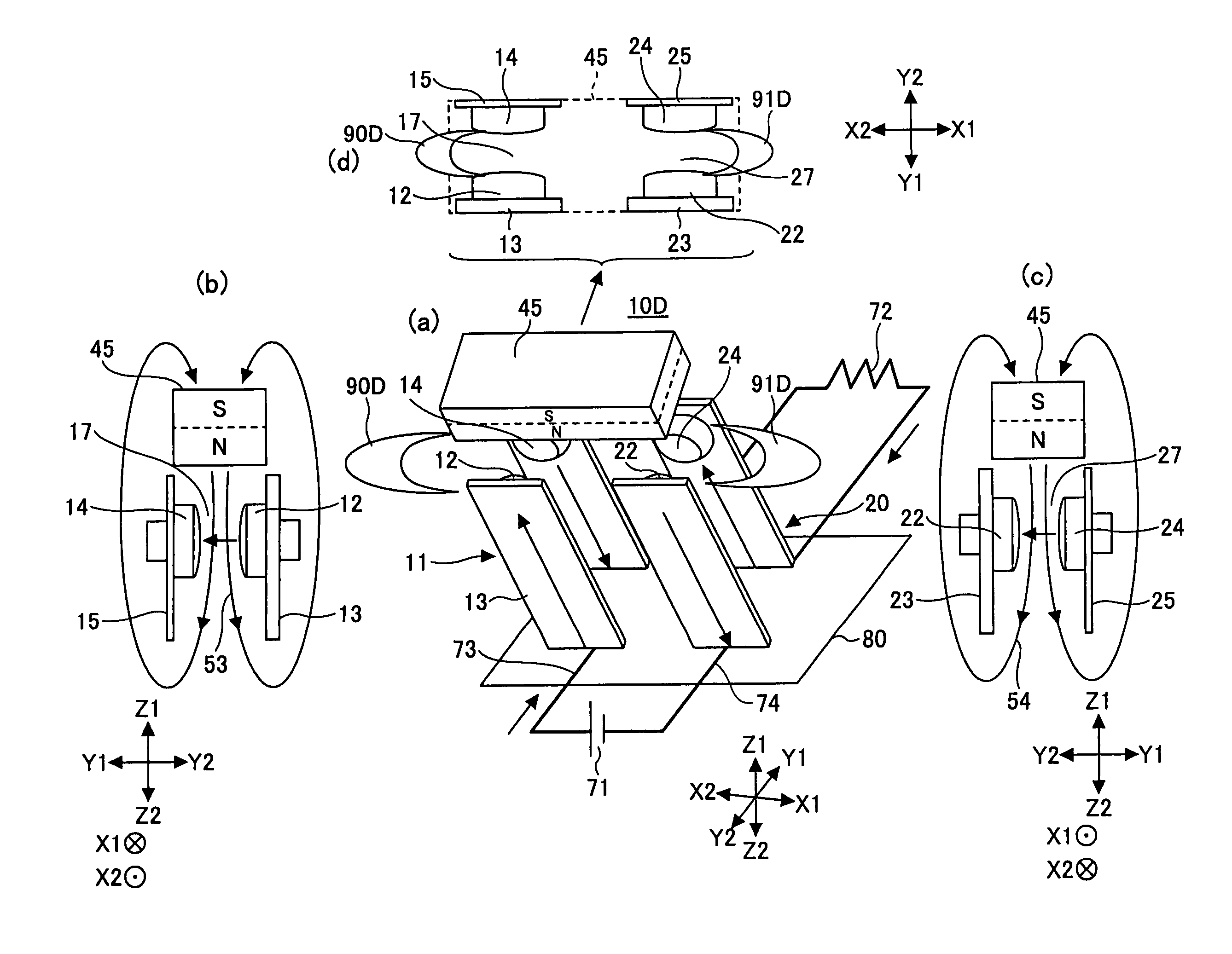
[0116]FIG. 10 is a schematic diagram showing a relay 10D according to the present invention.

[0117]FIG. 11 is a perspective view of the relay 10D, showing the relay 10D through a case 110D thereof.

[0118]FIGS. 12A through 12D are a top (Z1-side) cut-away view, an X2-side cut-away view, a Y2-side cut-away view, and a bottom (Z2-side) plan view, respectively, of the relay 10D.

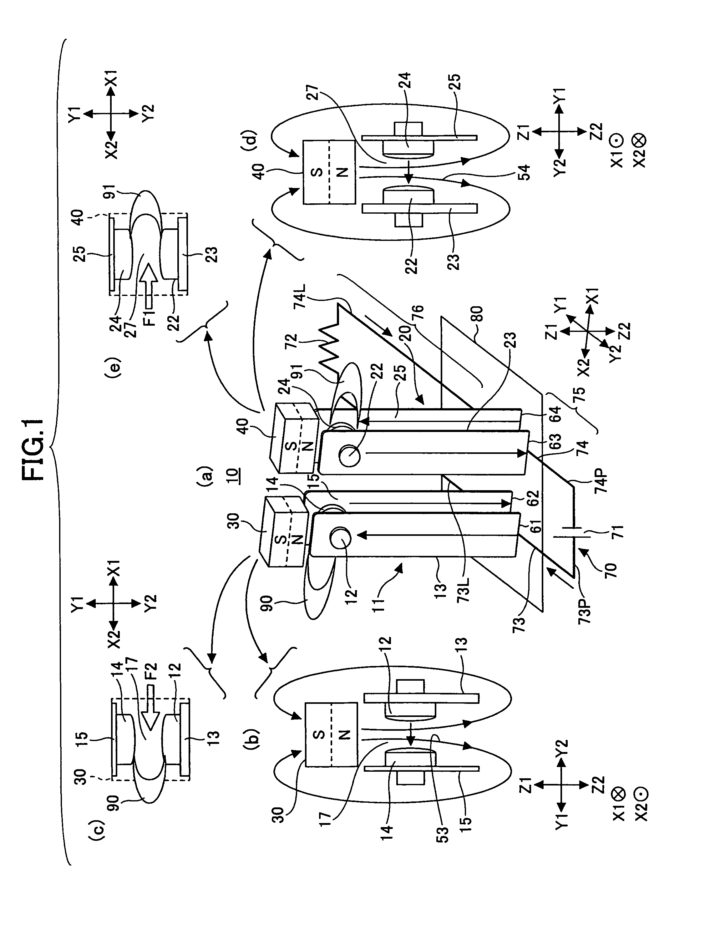
[0119]The relay 10D of the third embodiment has the same configuration as the relay 10 shown in FIG. 1 except that the first and second permanent magnet pieces 30 and 40 of the relay 10 shown in FIG. 1 are replaced with a common, single permanent magnet piece 45.

[0120]The permanent magnet piece 45 has a long, narrow rectangular parallelepiped shape extending over the gap 17 and the gap 27 with its north pole on the Z2 side and its south pole on the Z1 side. This configuration with the monolithic permanent magnet piece 45 is possible because of the configuration of applying magnetic fields of the same orientation on...


PUM


Abstract

A relay having a first opening and closing part including an openable and closable first gap; a second opening and closing part including an openable and closable second gap, the second opening and closing part being placed side by side with the first opening and closing part so that the first gap and the second gap are arranged side by side; a magnetization driving part to cause the first opening and closing part and the second opening and closing part to simultaneously operate; and a permanent magnet to apply a magnetic field on the first and second gaps in the same direction.

Description

BACKGROUND OF THE INVENTION[0001]1. Field of the Invention[0002]The present invention relates to relays, and more particularly to a direct current high voltage control relay employable in a circuit necessary to interrupt a high-voltage direct current.[0003]2. Description of the Related Art[0004]A high-voltage direct current flows through some circuits such as a circuit near the battery of an electric car and the circuit of an uninterruptible power supply (UPS) that is activated to supply power to a computer system in the case of an outage of commercial power to the computer system.[0005]In the case of applying a relay to such circuits, when the paired contacts of the relay in contact with each other are separated from each other, an arc current flows between the contacts because of the action of a high voltage on the relay, and this arc current damages the contacts so as to reduce the useful service life of the relay.[0006]A unit that opens and closes the high-voltage direct-current...

Claims


Application Information

Patent Timeline
Patent Type & Authority Patents(United States)
IPC IPC(8): H01H51/22
CPCH01H9/443H01H51/06H01H2050/049
Inventor YUBA, TAKASHITAKANO, SATOSHISASO, HIROFUMI
Owner FUJITSU COMPONENENT LTD
Why Eureka
Try Eureka