Machine for decreasing force exerted on maize during harvesting

a technology of maize and force, which is applied in the field of machines for harvesting maize, can solve the problems of high-speed impact of cobs on the top surfaces of stripper plates, detachment of maize grains from the cores of cobs, and special sensitive problems, and achieve the effect of reducing the impact of cobs on strippers

Active Publication Date: 2012-06-12
OLIMAC
View PDF20 Cites 28 Cited by
  • Summary
  • Abstract
  • Description
  • Claims
  • Application Information

AI Technical Summary

Benefits of technology

[0008]The object of the present invention is to provide a machine for harvesting maize that will enable reduction of the loss of useful crop due to the removal of the grains from the cobs.
[0010]In this way, when a cob comes into contact with the top surfaces of the stripper plates, the plates drop down against the action of the respective spring devices and dampen the impact of the cob on the stripper plates. The detachment of the cobs hence occurs in a gentler way, and the detachment of the grains of maize from the cores of the cobs is reduced considerably.

Problems solved by technology

This leads to a high-speed impact of the cobs against the top surfaces of the stripper plates.
One drawback of this type of machine is that the impact of the cobs on the stripper plates causes a detachment of the grains of maize from the cores of the cobs.
This problem becomes particularly sensitive when harvesting very dry maize.
On the other hand, in the case of dry maize, the grains detach easily from the core and the impact of the cobs at high speed on the stripper plates leads to a loss of useful crop on account of the removal of the grains from the cobs.

Method used


Image

  • Machine for decreasing force exerted on maize during harvesting
  • Machine for decreasing force exerted on maize during harvesting
  • Machine for decreasing force exerted on maize during harvesting

Examples


Embodiment Construction

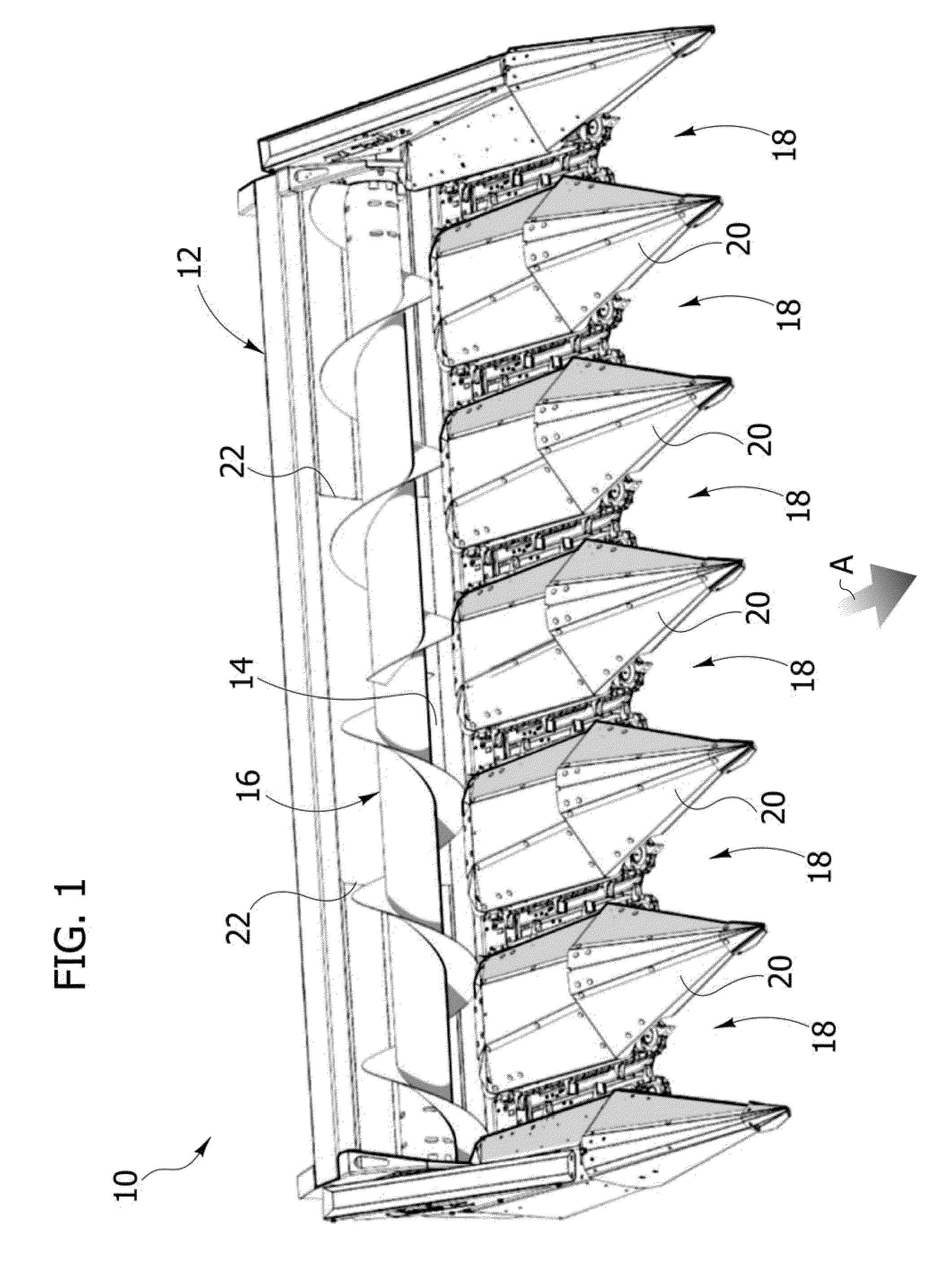
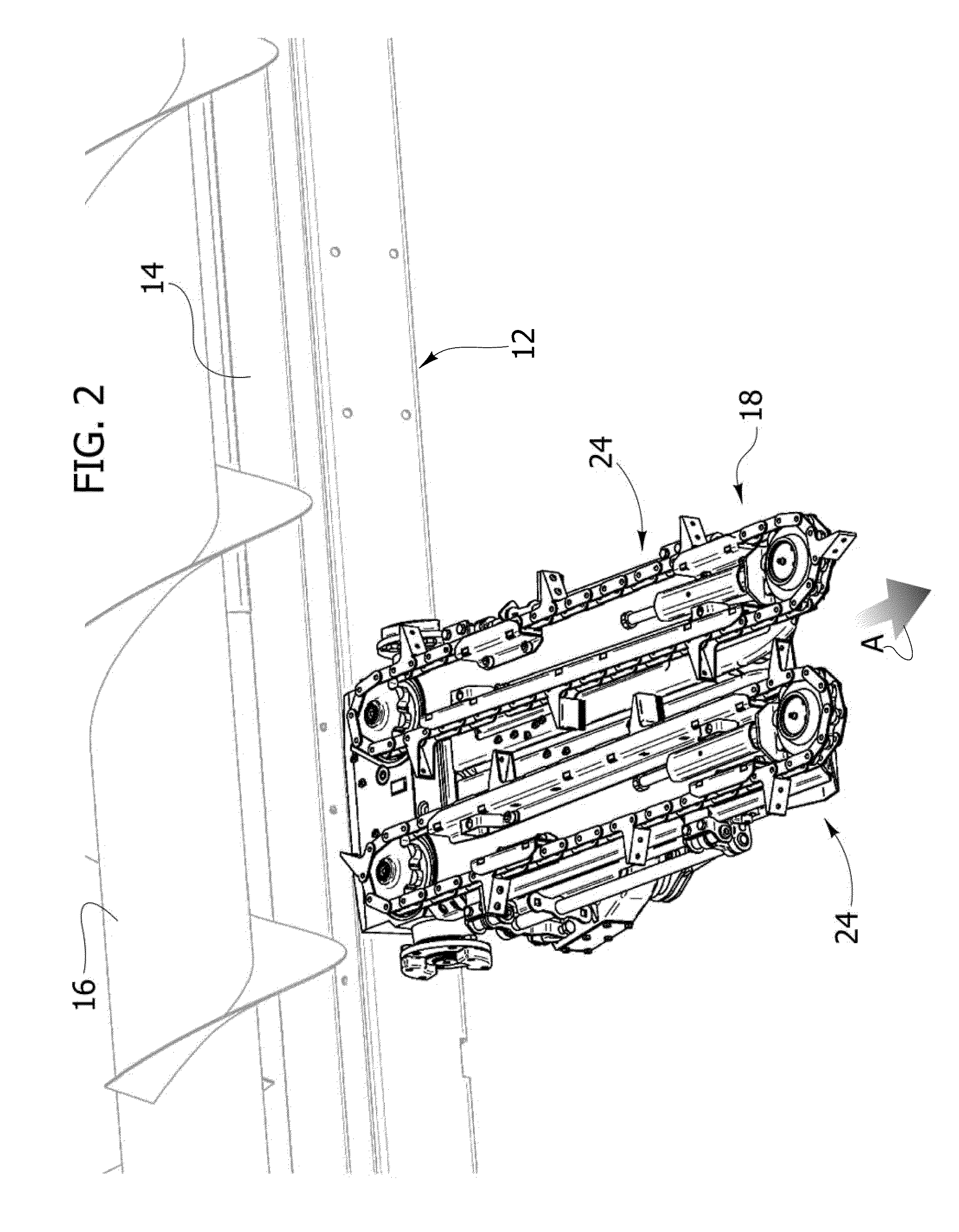
[0016]With reference to FIG. 1, designated by 10 is a machine for harvesting maize designed to be applied to the front part of a combine harvester for harvesting maize of a conventional type (not illustrated). The machine 10 comprises a supporting structure 12 equipped with means (not illustrated) for connection to the combine harvester. The supporting structure 12 has a transverse conveying channel 14, associated to which is a worm conveyor 16.

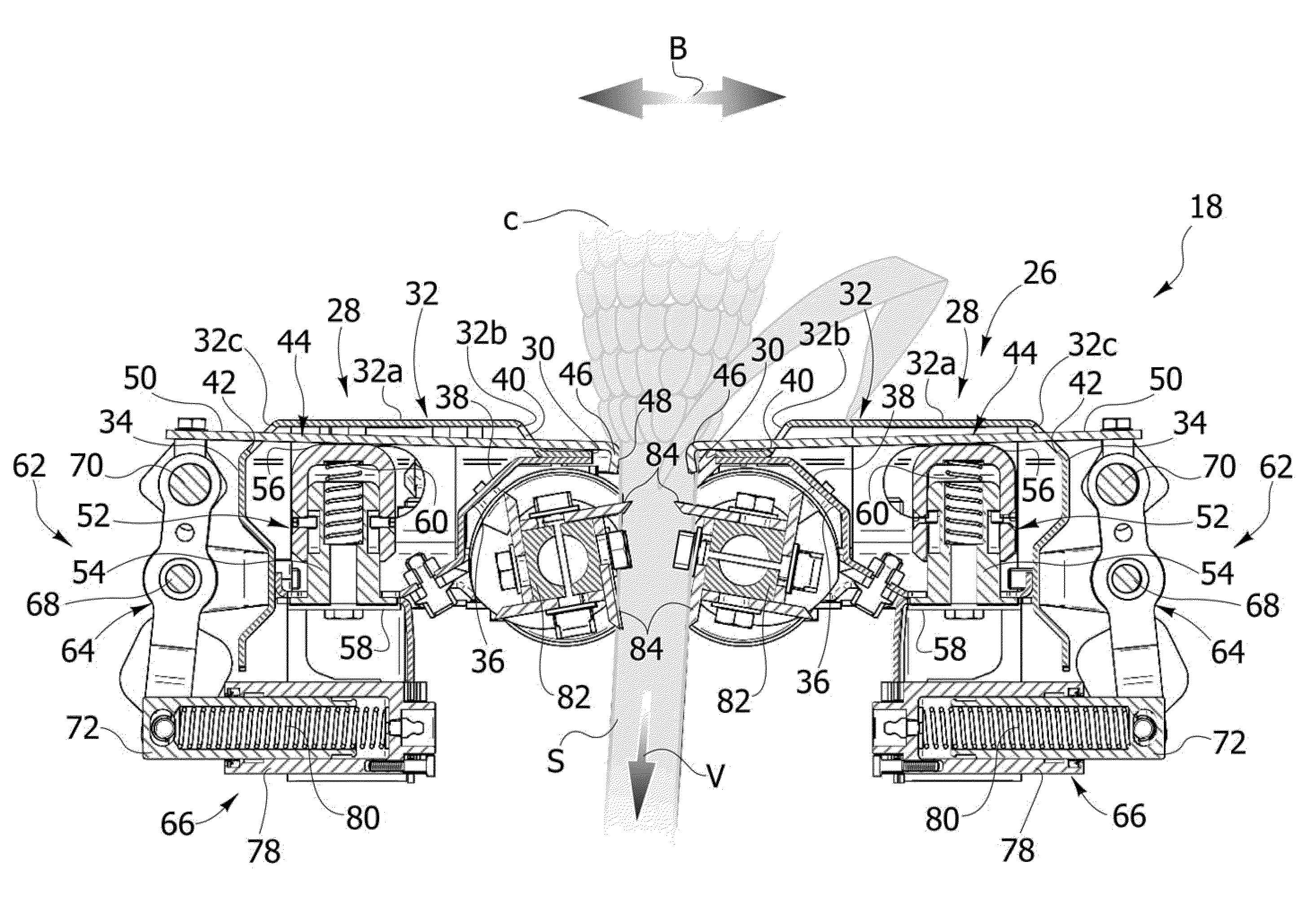
[0017]The supporting structure 12 carries a plurality of harvesting units 18 set alongside one another in a transverse direction with respect to the direction of advance of the machine 10, indicated by the arrow A in FIG. 1. Separation prongs 20 are arranged between adjacent harvesting units 18. The harvesting units 18 carry out detachment of the cobs from the maize stalks in the way that will be described in what follows. The harvesting units 18 convey the cobs towards the conveying channel 14. The worm conveyor 16 conveys the cobs contained...


PUM


Abstract

A machine for harvesting maize includes a supporting structure carrying a plurality of harvesting units set alongside one another in a transverse direction. Each harvesting unit includes a framework fixed with respect to the supporting structure and includes two box sections set at a distance from one another in a transverse direction by an empty space elongated in a longitudinal direction and two stripper plates carried by respective box sections. The stripper plate has respective edges facing one another that extend on opposite sides in the empty space, and the facing edges of the stripper plates form a squeezing channel. A pair of counter-rotating traction rollers are arranged underneath the squeezing channel. The stripper plates are mobile in a vertical direction with respect to the respective box sections and are associated to respective spring devices that push the stripper plates elastically towards a raised position.

Description

CROSS-REFERENCE TO RELATED APPLICATIONS[0001]This application claims benefit of European patent application number 09425513.0, filed Dec. 18, 2009, which is herein incorporated by reference.BACKGROUND OF THE INVENTION[0002]1. Field of the Invention[0003]The present invention relates to a machine for harvesting maize, designed to be applied to the front part of a combine harvester.[0004]2. Description of the Related Art[0005]Machines for harvesting maize of the most widespread type comprise a supporting structure designed to be fixed to the thresher and carrying a plurality of harvesting units set alongside one another in a transverse direction. Each harvesting unit is dedicated to the harvesting of a row of maize plants. Each harvesting unit usually comprises a fixed framework carrying two stripper plates. Said stripper plates have respective edges facing one another that form a squeezing channel for the maize stalks. Each harvesting unit comprises a pair of counter-rotating tractio...

Claims


Application Information

Patent Timeline
Patent Type & Authority Patents(United States)
IPC IPC(8): A01D45/02A01D45/10
CPCA01D45/021
Inventor CARBONI, LORENZO
Owner OLIMAC
Why Eureka
Try Eureka