
Socket structure with duplex electrical connection

a socket structure and duplex technology, applied in the direction of coupling device connection, air-break switch, coupling protective earth/shielding arrangement, etc., can solve the problem of inconvenience and achieve the effect of simple and convenient way

Active Publication Date: 2012-06-12
KIWI CONNECTION LLC
View PDF6 Cites 37 Cited by
  • Summary
  • Abstract
  • Description
  • Claims
  • Application Information

AI Technical Summary

Benefits of technology

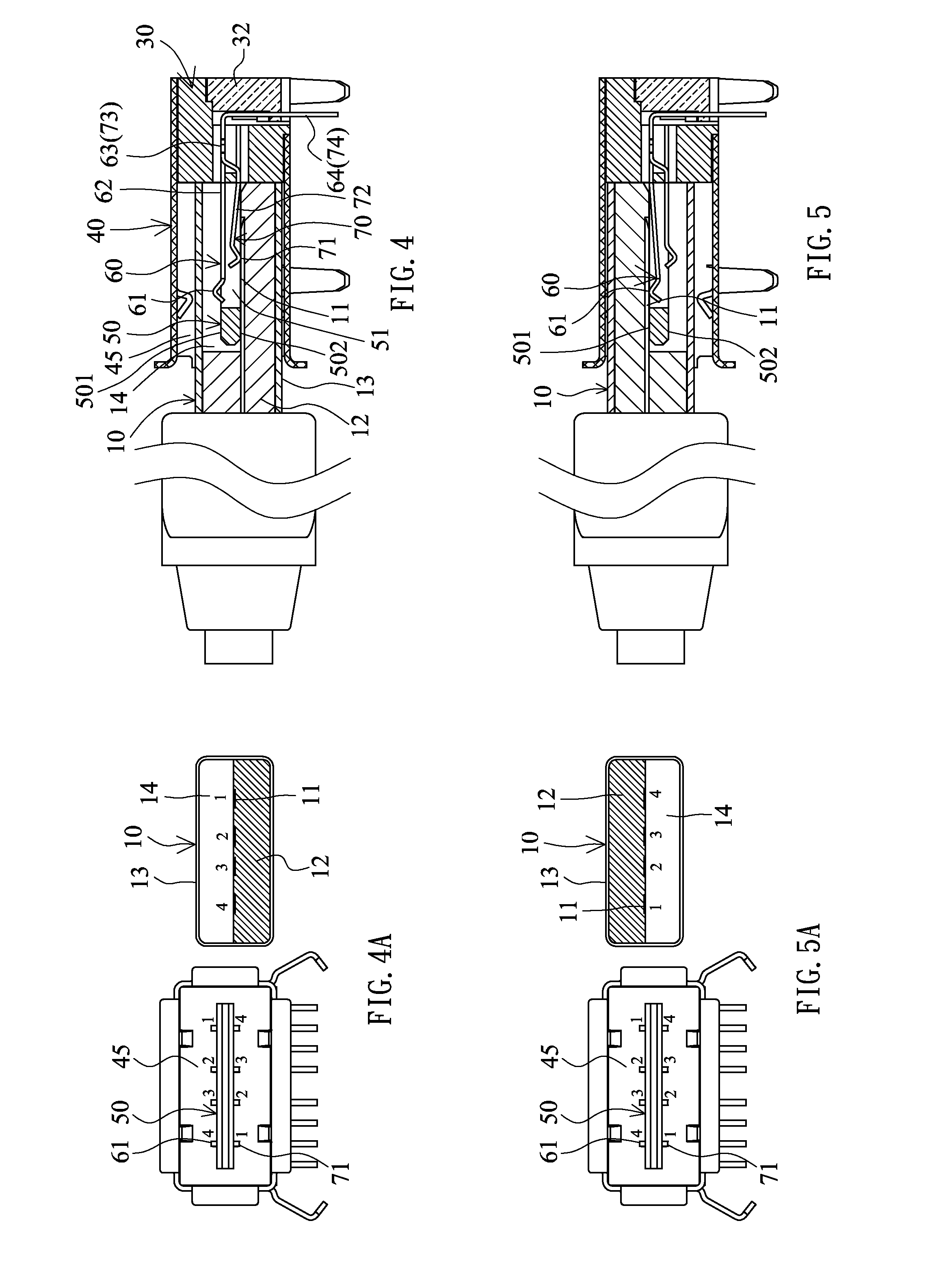
[0009]It is therefore an object of the invention to provide a socket structure with duplex electrical connection, wherein a plug may be normally and oppositely inserted into the socket structure to create electrical connection in a simple and easy way.
[0013]Yet still another object of the invention is to provide a socket structure with duplex electrical connection, wherein at least one side of a metal housing of the socket structure projects inwardly to form at least one laterally elastically movable elastic sheet, and when a plug is inserted into a connection slot, the at least one elastic sheet may rest against the plug or the tongue to prevent the plug from being turned to break the tongue.

Problems solved by technology

The user often has to insert the USB plug twice in an inconvenient manner.

Method used


Image

  • Socket structure with duplex electrical connection
  • Socket structure with duplex electrical connection
  • Socket structure with duplex electrical connection

Examples


Embodiment Construction

[0096]The present invention will be apparent from the following detailed description, which proceeds with reference to the accompanying drawings, wherein the same references relate to the same elements.

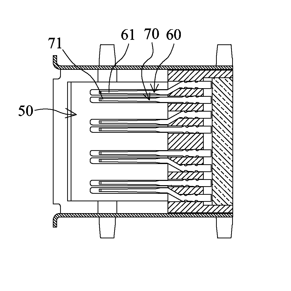
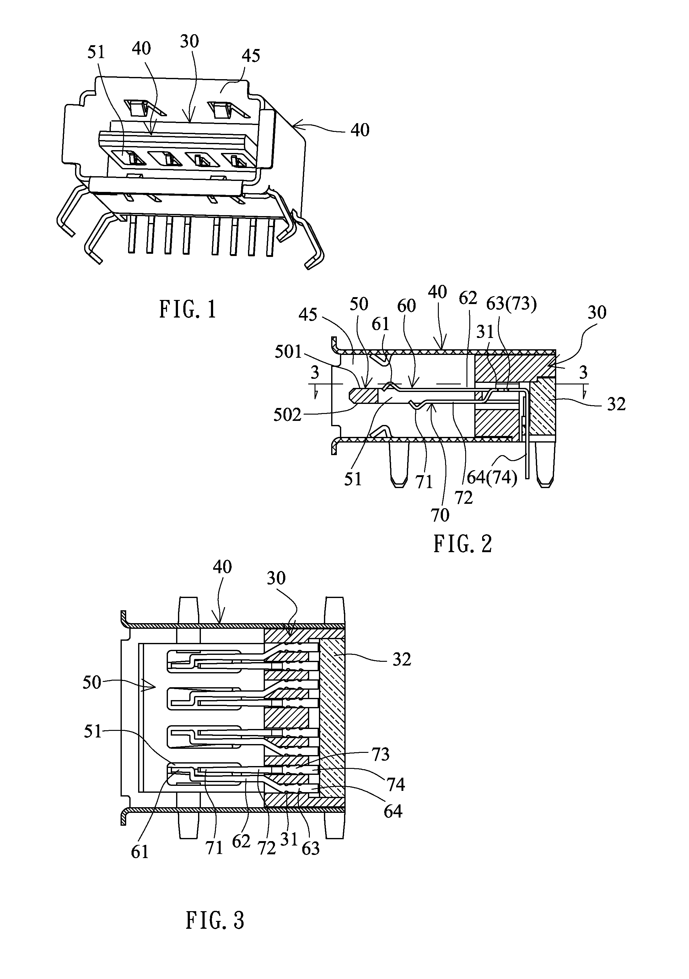
[0097]Referring to FIGS. 1 to 3, a USB 2.0 socket of this embodiment includes a plastic base 30, a metal housing 40, a tongue 50, one row of first terminals 60 and one row of second terminals 70.

[0098]The plastic base 30 has one row of terminal slots 31, and a rear cover 32 covers a rear end of the plastic base 30 from bottom to top.

[0099]The metal housing 40 covers the plastic base 30. A front section of the metal housing is formed with a connection slot 45, which may be electrically connected to a USB 2.0 plug.

[0100]The tongue 50 and the plastic base 30 are integrally injection molded together. The tongue 50 has a first surface 501 and a second surface 502 disposed opposite the first surface 501, and is horizontally disposed on the front end of the plastic base 30 and at a middle of...


PUM


Abstract

A socket structure includes a base; a slot, disposed on one end of the base and to be connected to one plug having one row of terminals; a tongue disposed on a front end of the base and within the slot so that chambers of the slot on two sides of the tongue may be normally and oppositely inserted and positioned into the slot; one row of first contacts separately arranged on one surface of the tongue, wherein each first contact is electrically connected to a first pin extending out of the base; and one row of second contacts separately arranged on the other surface of the tongue. Each second contact is electrically connected to a second pin extending out of the base. When the plug is inserted into the slot, the row of terminals of the plug are electrically connected to the row of first or second contacts.

Description

BACKGROUND OF THE INVENTION[0001]1. Field of the Invention[0002]The invention relates to an electrical connector, and more particularly to a socket structure with duplex electrical connection.[0003]2. Related Art[0004]The most popular signal transmission specification of the modern computer apparatus is the universal serial bus (USB). A connector socket and a transmission cable satisfying this specification may make peripheral apparatuses, such as a mouse, a keyboard and the like, which are externally connected to the computer, be immediately detected and used by the computer.[0005]Only one surface of the USB plug has one row of connection terminals. So, one surface of a tongue of the current USB socket has one row of connection terminals. In use, the USB plug has to be correctly inserted so that the connection terminals of the USB plug and the USB socket may be electrically connected together.[0006]In order to ensure the inserted USB plug to be electrically connected to the USB soc...

Claims


Application Information

Patent Timeline
Patent Type & Authority Patents(United States)
IPC IPC(8): H01H33/666H01R24/58
CPCH01R23/10H01R27/00H01R24/62H01R24/60
Inventor TSAI, CHOU HSIEN
Owner KIWI CONNECTION LLC
Learn More