
Low-voltage connection with safety circuit and method for determining proper connection polarity

a low-voltage connection and safety circuit technology, applied in the direction of safety/protection circuits, coupling device connections, instruments, etc., can solve the problems of adding component costs, reduce or prevent inductive voltage spikes, reduce and/or prevent damage to sensitive low-voltage electronics, the effect of adding component costs

Inactive Publication Date: 2012-06-12
ENERGY SAFE TECH
View PDF20 Cites 48 Cited by
  • Summary
  • Abstract
  • Description
  • Claims
  • Application Information

AI Technical Summary

Benefits of technology

[0007]When the safety circuit determines that no unsafe conditions exist and that it is safe to connect the two low-voltage systems, the safety circuit may connect the two systems by way of a “soft start.” The soft start provides a connection between the two systems that is not instantaneous, but is instead provided over a period of time, such as tens of milliseconds, that reduces or prevents inductive voltage spikes on one or more of the low-voltage systems. The soft start procedure reduces and / or prevents damage to sensitive low-voltage electronics forming a part of one or more of the low-voltage systems.
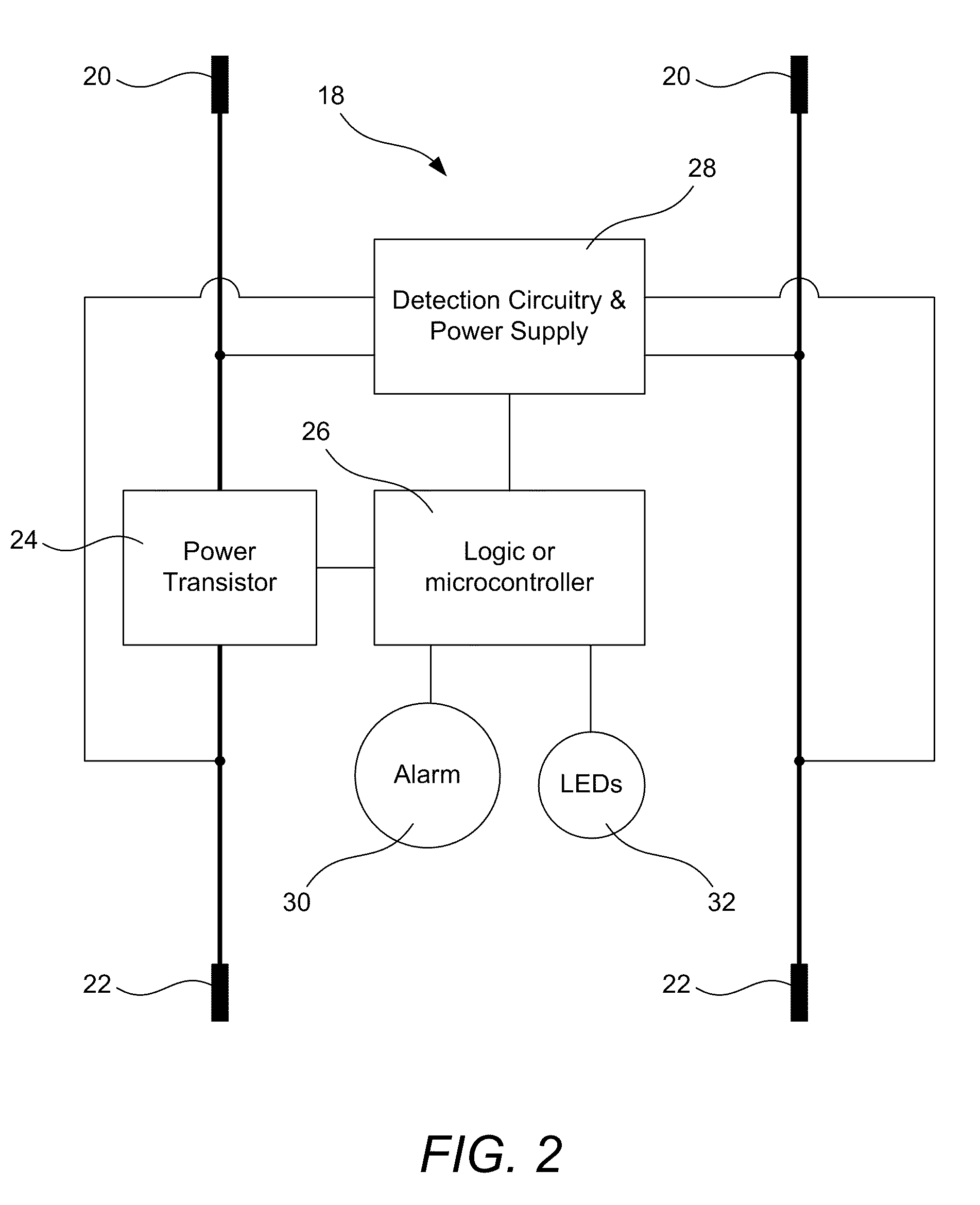
[0008]Some implementations of the invention utilize one or more high-current transistors as a switch to connect the two low-voltage systems. The one or more transistors are controlled by the safety circuit or control circuit that detects the condition at each end of the connection cable or cables. In other implementations providing automatic correction of attempted reversed-polarity connections, additional components are used to provide additional convenience. While such implementations provide no additional safety benefit over implementations not providing automatic polarity reversal as the connection is not completed when a reversed polarity is detected, the added convenience of not requiring manual polarity correction may justify the added component cost in some instances.

Problems solved by technology

In some instances, the safety circuit refuses to make a connection between the two low-voltage systems while an unsafe condition exists.
While such implementations provide no additional safety benefit over implementations not providing automatic polarity reversal as the connection is not completed when a reversed polarity is detected, the added convenience of not requiring manual polarity correction may justify the added component cost in some instances.

Method used


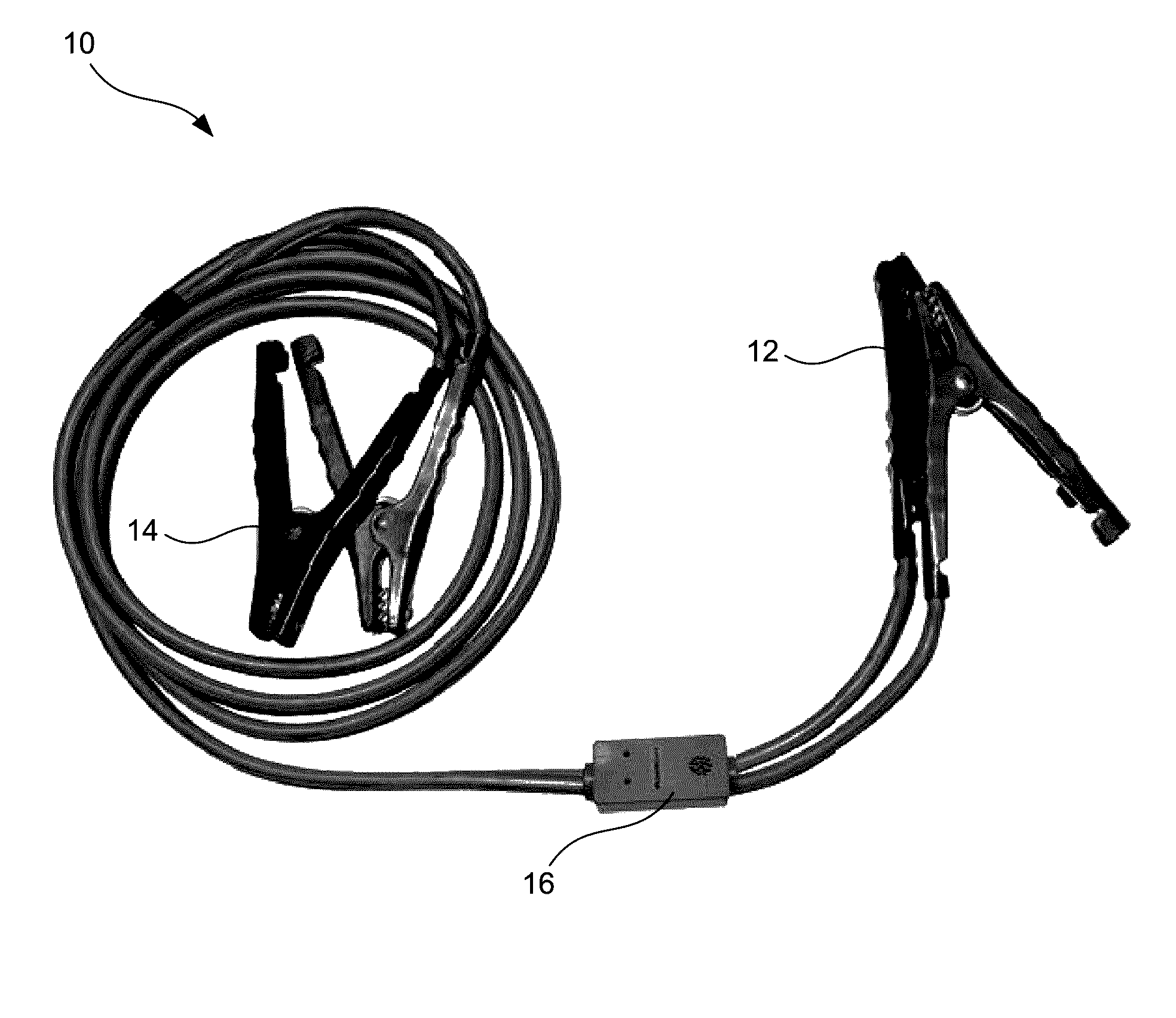
Image

  • Low-voltage connection with safety circuit and method for determining proper connection polarity
  • Low-voltage connection with safety circuit and method for determining proper connection polarity
  • Low-voltage connection with safety circuit and method for determining proper connection polarity

Examples


Embodiment Construction

[0020]A description of embodiments of the present invention will now be given with reference to the Figures. It is expected that the present invention may take many other forms and shapes, hence the following disclosure is intended to be illustrative and not limiting, and the scope of the invention should be determined by reference to the appended claims.

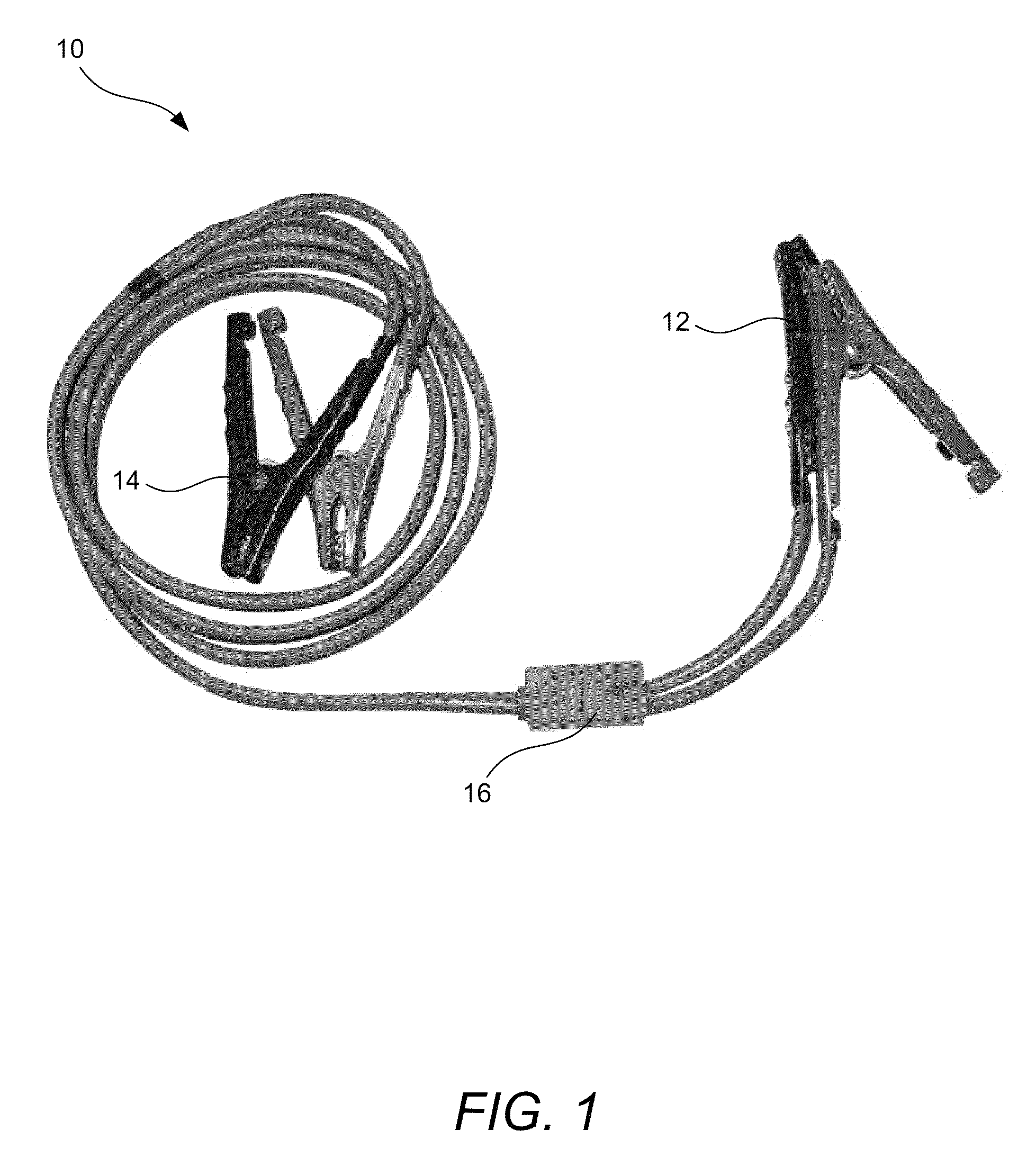
[0021]Embodiments of the invention provide a connecting cable or cables (such as jumper cables) between two low-voltage systems (such as batteries, battery-powered systems, or low-voltage systems incorporating one or more batteries) that includes a safety circuit. The safety circuit leaves the two low-voltage systems disconnected until it determines that it is safe to make a connection. If the safety circuit detects an unsafe condition, it responds to the unsafe condition in one or more of several fashions. In some instances, the safety circuit can internally reverse connection polarity to correct for incorrect connections between l...


PUM


Abstract

A safety circuit used in low-voltage connecting systems leaves the two low-voltage systems disconnected until it determines that it is safe to make a connection. When the safety circuit determines that no unsafe conditions exist and that it is safe to connect the two low-voltage systems, the safety circuit may connect the two systems by way of a “soft start” that provides a connection between the two systems over a period of time that reduces or prevents inductive voltage spikes on one or more of the low-voltage systems. When one of the low-voltage systems has a completely-discharged battery incorporated into it, a method is used for detection of proper polarity of the connections between the low-voltage systems. The polarity of the discharged battery is determined by passing one or more test currents through it and determining whether a corresponding voltage rise is observed.

Description

CROSS-REFERENCE TO RELATED APPLICATIONS[0001]This application claims the benefit of U.S. Provisional Application No. 61 / 175,696, filed May 5, 2009 and U.S. Provisional Application No. 61 / 118,511 filed Nov. 28, 2008.BACKGROUND OF THE INVENTION[0002]1. Field of the Invention[0003]The present invention relates to jumper cables and, more particularly, to jumper cables providing safety and soft start features.[0004]2. Background and Related Art[0005]Cables such as jumper cables are commonly used to connect two low-voltage (e.g. battery-powered) systems temporarily. However, the use of such cables can result in personal injury and equipment damage. For example, one instance where equipment damage or personal injury occurs is in the case of jump starting a car with a “dead” (i.e. partially- or totally-discharged) battery using a car with a good battery. During connection of jumper cables to jump start the car with the discharged battery, a spark may be created, and if the spark is in the v...

Claims


Application Information

Patent Timeline
Patent Type & Authority Patents(United States)
IPC IPC(8): G08B21/00
CPCH01R13/641H02J7/0034H02J7/00308
Inventor BAXTER, JEFFREYBAXTER, BRENTBAXTER, MICHAELHOLBROOK, TED
Owner ENERGY SAFE TECH
Learn More