
Processing and forwarding of message-signaled interrupts

a message-signaled interrupt and processing technology, applied in the direction of electric digital data processing, instruments, etc., can solve the problems of insufficient utilization of data value, lack of flexibility, limited notification destination to the processor,

Inactive Publication Date: 2012-06-12
SONY CORP
View PDF10 Cites 8 Cited by
  • Summary
  • Abstract
  • Description
  • Claims
  • Application Information

AI Technical Summary

Benefits of technology

[0008]It is desirable to realize flexible interrupt processing by utilizing a characteristic of an interrupt in a message format.

Problems solved by technology

However, when the interrupt issued to the processor is transmitted using the interrupt signal, a notification destination is limited to the processor, which lacks flexibility.
Furthermore, there arises a problem in that a characteristic of an MSI including address information and a data value is not sufficiently utilized.

Method used


Image

  • Processing and forwarding of message-signaled interrupts
  • Processing and forwarding of message-signaled interrupts
  • Processing and forwarding of message-signaled interrupts

Examples


first embodiment

1. First Embodiment

Example of Information Processing System Including Single Bridge Device

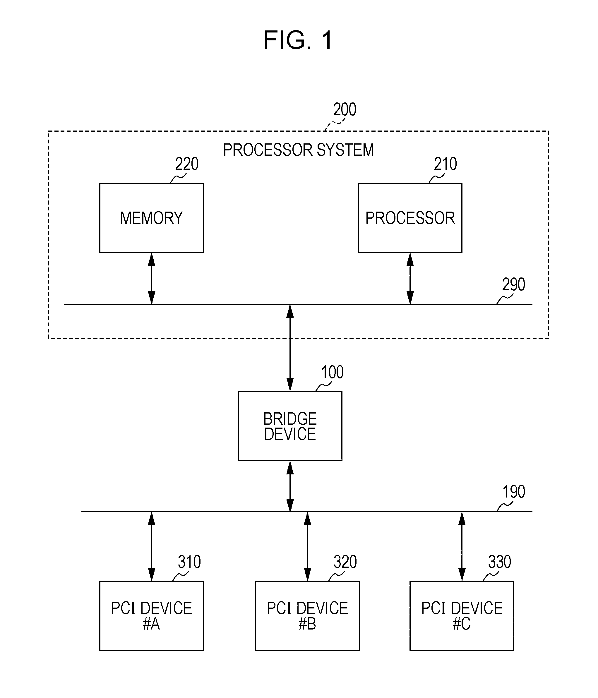
[0032]FIG. 1 is a diagram illustrating a configuration example of an information processing system according to a first embodiment of the present invention. The information processing system includes a bridge device 100, a processor system 200, and PCI (Peripheral Component Interconnect) devices 310 to 330.

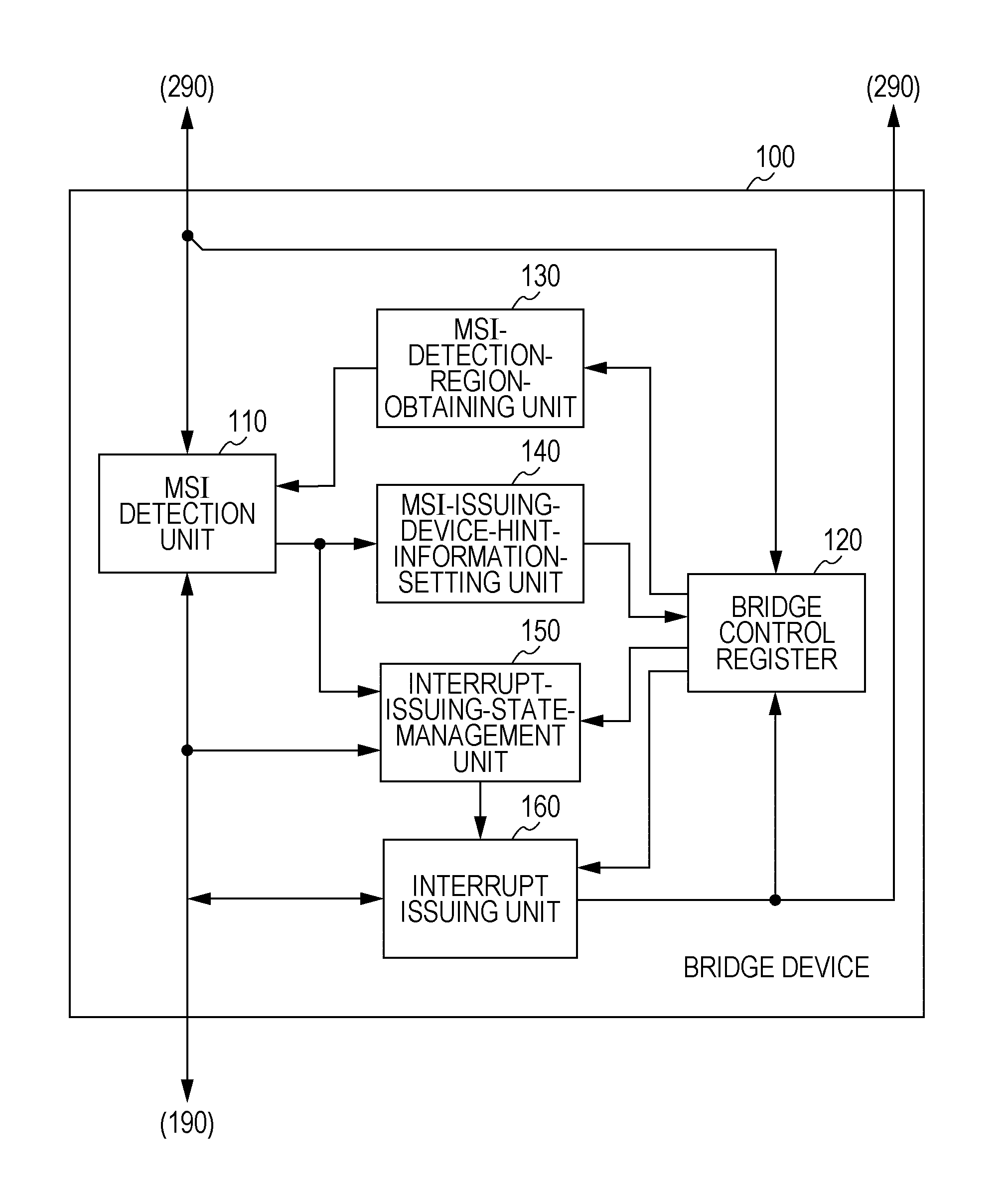
[0033]The bridge device 100 is connected between a processor bus 290 included in the processor system 200 and a PCI bus 190 located near the PCI devices 310 to 330, and enables mutual communication therebetween by changing a packet format and an electric characteristic. The bridge device 100 detects an interrupt in a message format transmitted through the bridge device 100 to thereby generate an interrupt in a new message format or a processor interrupt.

[0034]The processor system 200 includes a processor 210 and a memory 220 which are connected to each other through the processor bus 290. The...

second embodiment

2. Second Embodiment

Example of Information Processing System Including Several Bridge Devices

[0104]FIG. 14 is a diagram illustrating a configuration example of an information processing system according to a second embodiment of the present invention. The information processing system includes three bridge devices #A 101 to #C 103, two processor systems #A 201 and #B 202, and four PCI devices 310 to 340.

[0105]The bridge device #A 101 and the bridge device #B 102 are connected between a PCI bus 190 and the processor system #A 201 in series. Furthermore, the bridge device #C 103 is connected between the PCI bus 190 and the processor system #B 202. In terms of the relationship between the processor systems #A 201 and #B 202 and the PCI bus 190, the bridge devices #A 101 and #B 102 are connected to the bridge device #C 103 in parallel.

[0106]In this configuration example, each of the bridge devices #A 101 to #C 103 issues a new MSI in response to detection of an MSI issued from one of th...


PUM


Abstract

An interrupt detection apparatus includes a detection address region storing unit configured to store an address region, as a detection address region, to be detected in accordance with a first interrupt message having address information, an issuance interrupt information storing unit configured to store address information of a second interrupt message as issuance interrupt information, an interrupt message detection unit configured to determine that the first interrupt message corresponds to the detection address region, and an interrupt issuing unit configured to issue the second interrupt message having the issuance interrupt information when it is determined that the first interrupt message corresponds to the detection address region.

Description

CROSS REFERENCE TO RELATED APPLICATIONS[0001]The present application claims priority under 35 U.S.C. §119(a) to Japanese Patent Application JP 2008-290438, filed in the Japan Patent Office on Nov. 13, 2008, the entire content of which is hereby incorporated by reference.BACKGROUND OF THE INVENTION[0002]1. Field of the Invention[0003]The present invention relates to interrupt detection apparatuses, and particularly relates to an interrupt detection apparatus which detects an interrupt message including address information and an information processing system including the interrupt detection apparatus.[0004]2. Description of the Related Art[0005]When a processor or the like performs a normal operation, the operation can be switched to another operation by issuing an interrupt for interrupting the normal operation. In a computer system including a PCI (Peripheral Component Interconnect) bus, as a method for transmitting a notification representing an interrupt from a PCI device to a h...

Claims


Application Information

Patent Timeline
Patent Type & Authority Patents(United States)
IPC IPC(8): G06F13/24
CPCG06F13/24G06F13/14
Inventor KANAYA, HIDEKAZU
Owner SONY CORP
Learn More