Field tunable spin torque oscillator for RF signal generation

a field tunable spin torque and oscillator technology, applied in the field of perpendicular spin transfer oscillator, can solve the problems of inability to use gmr junction and tmr junction in the same device, and the resistance change of the mr junction to reflect the mol oscillation, and achieve the effect of promoting efficient magnetostatic coupling

Active Publication Date: 2012-06-19
HEADWAY TECH INC
View PDF10 Cites 78 Cited by
  • Summary
  • Abstract
  • Description
  • Claims
  • Application Information

AI Technical Summary

Benefits of technology

[0023]In a second embodiment, the features of the first embodiment are retained except the MOL in the STO stack is a single layer that may be a soft magnetic layer or a magnetic layer having a certain PMA. Preferably, the TMR sensing layer has a magnetic property, physical size, and thickness substantially the same as that of the MOL in order to promote efficient magnetostatic coupling between the two layers and induce a magnetization oscillation in the TMR sensing layer when the MOL is excited into an oscillation state.

Problems solved by technology

As a result, spin valve structures based on PMA are capable of scaling for higher packing density which is a key challenge for future MRAM (Magnetoresistive Random Access Memory) applications and other spintronic devices such as microwave generators.
However, when MOL layers 31-33 reach a stable magnetic oscillation with a significant amount of in-plane magnetization component, the relative angle between the magnetizations of MRL 1 and MOL 31-33 does not really change which makes it difficult to generate an electrical signal through the resistance change of the MR junction to reflect the MOL oscillation.
However, there are disadvantages associated with the prior art as pictured in FIG. 1.
In other words, a GMR junction and a TMR junction cannot be used in the same device in a configuration where a high density current flows through both structures.
This dilemma significantly limits the FIG. 1 structure applicability for actual STO RF signal generation.
The change to irregular oscillations and lower power is especially not desirable when uniform and high power MOL oscillation is required on a continuous basis for optimum performance while characterization of oscillation frequency is only needed occasionally, for example, when the PSTO is used as a RF field generator in a magnetic recording device.
Another disadvantage of the FIG. 1 structure is that the PMA layer 32 is separated from the lower junction layer 2 by a soft magnetic layer 31.

Method used


Image

  • Field tunable spin torque oscillator for RF signal generation
  • Field tunable spin torque oscillator for RF signal generation
  • Field tunable spin torque oscillator for RF signal generation

Examples


Embodiment Construction

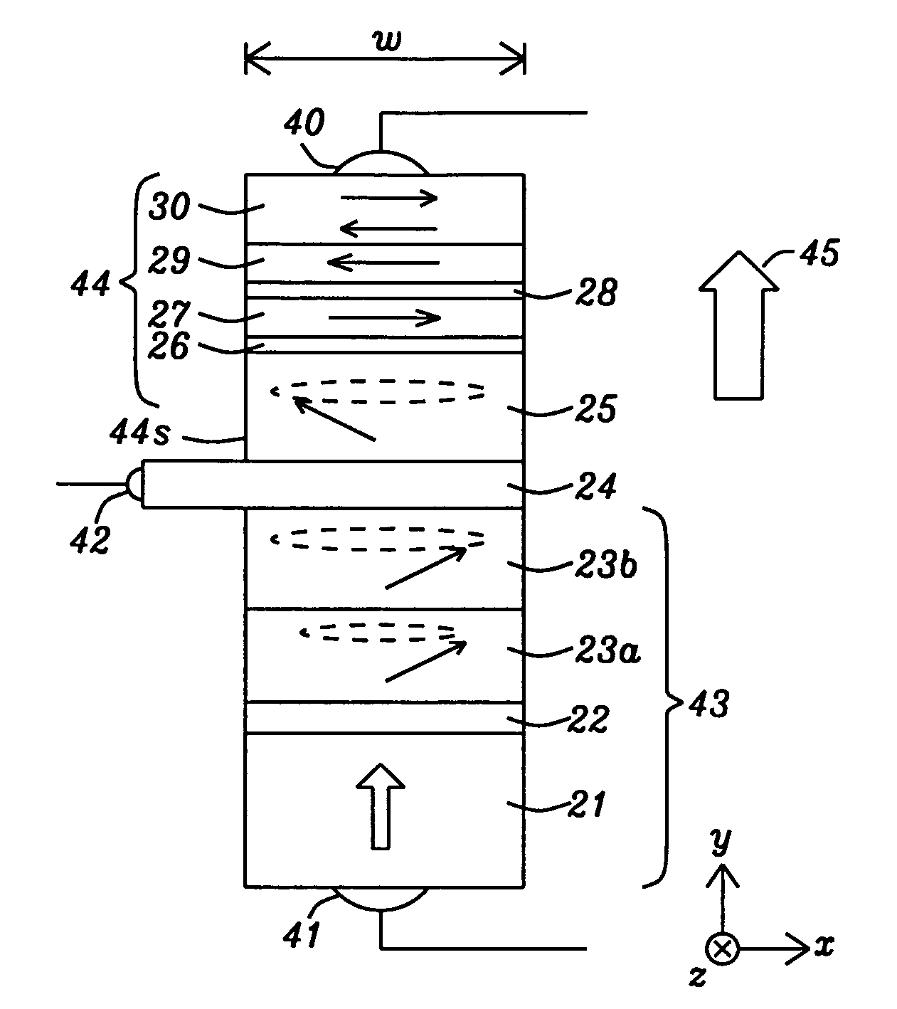
[0033]The present invention is a PSTO device wherein a high density STO current is isolated from a low density RF generation current. The perpendicular spin torque oscillator may be employed as a RF field generator in a magnetic recording head or may serve as a reference oscillator or directional microwave transmitter in devices such as cell phones, radar systems, and computer chips. The magnetic oscillation layer (MOL) as described herein is considered a “free” ferromagnetic layer in that its magnetization orientation is free to change (oscillate) in the presence of a direct current flowing perpendicular to the plane of the MOL and under the influence of an applied magnetic field. Magnetic layers as defined herein are ferromagnetic layers.

[0034]Referring to FIG. 4, a first embodiment of the present invention is depicted wherein a PSTO device is comprised of a STO component 43 and a RF generation component 44 hereafter referred to as “RF generator” or “MR sensor” that are separated ...


PUM


Abstract

A spin transfer oscillator (STO) device is disclosed with a giant magnetoresistive (GMR) junction comprising a magnetic resistance layer (MRL) / spacer / magnetic oscillation layer (MOL) configuration, and a MR sensor including a sensing layer / junction layer / reference layer configuration. MOL and sensing layer are magnetostatically coupled and separated by a conductive spacer. MRL has perpendicular magnetic anisotropy while MOL and sensing layer have a Mst (saturation magnetization×thickness) value within ±50% of each other. When a magnetic field is applied perpendicular to the planes of the MOL and a high density current flows from the conductive spacer to the MRL, a MOL oscillation state with a certain frequency is induced. Consequently, the sensing layer oscillates with a similar RF frequency and when a low density current flows across the MR sensor, an AC voltage signal is generated to determine the sensing layer frequency that can be varied by adjusting the applied field.

Description

RELATED PATENT APPLICATION[0001]This application is related to the following: Ser. No. 12 / 800,196, filing date May 11, 2010; assigned to the same assignee and herein incorporated by reference in its entirety.FIELD OF THE INVENTION[0002]The invention relates to a perpendicular spin transfer oscillator (PSTO) used for thin film applications such as a RF field generator in spintronic device, and in particular to a PSTO structure having a three electrical terminal structure wherein a high density current is flowed through a GMR junction to induce a magnetic oscillation layer into an oscillation state; and a low density RF signal generation current is flowed though an adjacent TMR junction for sensing an oscillation frequency.BACKGROUND OF THE INVENTION[0003]Spin transfer (spin torque) devices are based on a spin-transfer effect that arises from the spin dependent electron transport properties of ferromagnetic-spacer-ferromagnetic multilayers. When a spin-polarized current transverses a ...

Claims


Application Information

Patent Timeline
Patent Type & Authority Patents(United States)
IPC IPC(8): H03L7/26
CPCH03B15/006
Inventor ZHOU, YUCHENZHANG, KUNLIANGWANG, POKANGSMYTH, JOE
Owner HEADWAY TECH INC
Why Eureka
Try Eureka