Mounting with shock and harmonic vibration dampener

a technology of harmonic vibration and dampener, which is applied in the direction of sighting devices, cartridge extractors, weapons, etc., can solve the problems of harmonic vibration, shock wave and harmonic vibration, damage or destruction of almost any electro-optical device, etc., and achieve the effect of dampening the harmonic vibration and the shock wav

Active Publication Date: 2012-06-26
SWAN RICHARD E
View PDF21 Cites 27 Cited by
  • Summary
  • Abstract
  • Description
  • Claims
  • Application Information

AI Technical Summary

Benefits of technology

[0017]The present invention seeks to provide a unique dampening structure incorporated into an accessory mount in a manner that dampens shock waves and the resulting harmonic vibration cause by operation of the firearm.

Problems solved by technology

One of the issues of mounting sensitive electro-optic components on a weapon is that shock waves and harmonic vibration resulting from operation of the weapon are transmitted through the weapon and mounts into the mounted component.
Shock waves and the resultant harmonic vibrations that travel through the mechanical structures of the weapon will fatigue, damage or destroy almost any electro-optical device over time.
While some of the sighting devices that are employed with a firearm may be able to endure the shocks, many more are damaged and ultimately fail as a result of the transferred shock waves and harmonic vibration.
All branches of the military are reporting increased instances of field failure of these expensive, highly sensitive optic components on all types of weapons.
However, failures are particularly distinguished on the more powerful, higher caliber weapons.
In addition to recoil, every weapon also experiences higher frequency shock waves and harmonic vibration caused by slamming of the moving parts of weapon against each other.
More often, vibration is undesirable, wasting energy and creating unwanted disturbances.
While existing buffer spring systems are intended to capture the energy of the rearward thrust of the bolt, they are not designed to dampen higher frequency shock waves and harmonic vibrations, which are distinctly different from recoil.
These springs are not intended to absorb recoil shock.
While each of the devices of the prior art is generally effective for its intended purpose, i.e. absorbing recoil thrust, none are directed at the unique problem of absorbing high frequency shock waves and harmonic vibration, which can destroy sensitive electro-optic devices.

Method used


Image

  • Mounting with shock and harmonic vibration dampener
  • Mounting with shock and harmonic vibration dampener
  • Mounting with shock and harmonic vibration dampener

Examples


Embodiment Construction

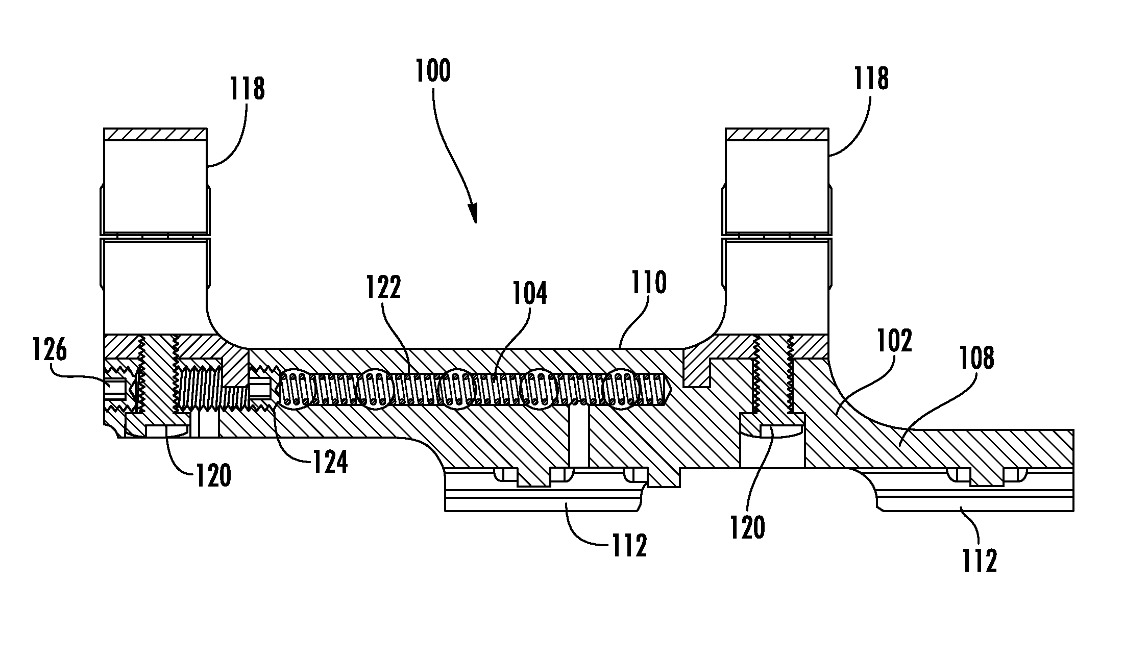
[0038]Now referring to the drawings, a mounting assembly constructed in accordance with the teachings of the present invention is shown and generally illustrated at 100 in FIGS. 3-7.

[0039]The mounting assembly 100 generally includes a body 102, a dampening structure 104, and a clamping assembly 106. It is noted that the illustrated mount includes a pair of clamping assemblies 106. However, for purposes of this description we will refer to a single clamping assembly 106.

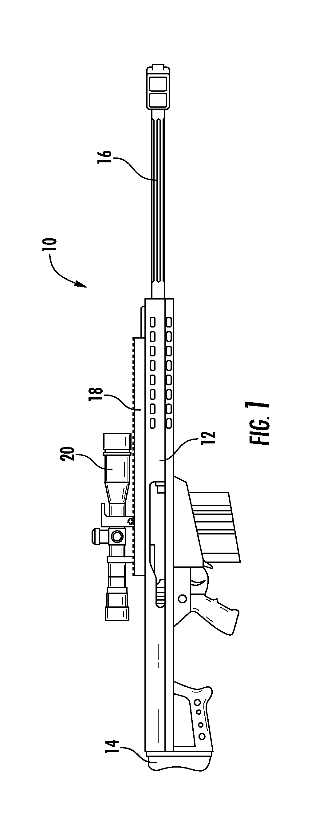
[0040]The body 102 includes a lower portion 108 that is configured to engage the dovetail rail 18 found on most modern combat weapons and an upper portion 110 that can take on a variety of configurations depending on the accessory that is to be mounted thereon. The lower portion 108 of the body has a pair of first engagement members 112 extending downwardly along one side thereof for engaging one side of the dovetail rail 18. Opposite the first engagement members 112, a boss formation 114 is provided adjacent the side...


PUM


Abstract

A mounting assembly for attaching an accessory to a dovetail rail interface on a firearm includes a body having a lower portion and an upper portion. The lower portion is configured to engage the dovetail rail interface and the upper portion is configured to receive and retain an accessory such as a scope or aiming device. A spring dampening structure resides within the body of the assembly wherein dampening structure is configured to dampen shock waves and harmonic vibration transferred into the body from operation of the firearm. A clamping assembly is configured to releasably clamp the body to the dovetail rail interface.

Description

BACKGROUND OF THE INVENTION[0001]The present invention relates generally to modular integrated accessory mounting assemblies for combat weapons. More specifically, the present invention relates to a unique dampening structure incorporated into an accessory mount in a manner that dampens shock waves and the resulting harmonic vibration cause by operation of the firearm.[0002]As the field of combat and commercial weaponry expands, numerous add-on enhancements have become available for attachment to standard firearms, thereby significantly upgrading the capability of the firearm. Of particular interest in the area of combat weapons are the well-known M16 / M4 weapon systems (M16 and M4 are trademarks of Colt Defense, Inc.), the FNH™ SCAR™ weapon system (FN and SCAR are trademarks of FN Herstal, S.A., and the Barrett™ family of high caliber sniper weapons (Barrett is a trademark of Barrett Firearms Mfg., Inc.). However, the concepts of the present invention are equally applicable to all f...

Claims


Application Information

Patent Timeline
Patent Type & Authority Patents(United States)
IPC IPC(8): F41G1/38F41C27/00
CPCF41G1/38F41G11/002F41G11/003
Inventor SWAN, RICHARD E.
Owner SWAN RICHARD E
Why Eureka
Try Eureka