Controller and control method for hybrid system

a control method and hybrid technology, applied in mechanical energy handling, mechanical equipment, transportation and packaging, etc., can solve the problems of displaced center line, vibration and noise, and unlikely to cause vibration in the hybrid vehicle, and achieve the effect of suppressing the vibration of the vehicl

Active Publication Date: 2021-04-06
TOYOTA JIDOSHA KK
View PDF2 Cites 0 Cited by
  • Summary
  • Abstract
  • Description
  • Claims
  • Application Information

AI Technical Summary

Benefits of technology

[0007]The above-described configuration causes the engine-side rotating body and the motor-side rotating body to rotate integrally when the clutch is in the engaged state. In this state, the position of the center of gravity of the engine-side rotating body and the position of the center of gravity of the motor-side rotating body are more separated from each other than before the clutch performs the balance control. Thus, when viewed in the direction of the center line of rotation, the center of gravity of the entirety of the components that rotate integrally is closer to the center line of rotation than before the balance control is performed. This reduces the displacement of the center of gravity of the entirety of the components that rotate integrally from the center line of rotation. As a result, even if the clutch is in the engaged state, so that the engine-side rotating body and the motor-side rotating body rotate integrally, vibration is unlikely to be caused in the hybrid vehicle.Example 2
[0009]In a comparative example, in a state in which the internal combustion engine and the electric motor are in a stopped state, the motor-side rotating body and the motor-side rotating body are each in a stopped state such that the center of gravity is located below the center line of rotation due to by its own weight. Thus, if the clutch is engaged in this state to continue integral rotation of the engine-side rotating body and the motor-side rotating body, the engine-side rotating body and the motor-side rotating body rotate with the center of gravity of the entirety of the components that rotate integrally being significantly displaced from the center line of rotation. In contrast, the above-described configuration engages the engine-side rotating body and the motor-side rotating body with each other in a state in which the position of the center of gravity of the engine-side rotating body and the position of the center of gravity of the motor-side rotating body are separated from each other in the circumferential direction as compared to a state in which the positions of the centers of gravity are close to each other in the circumferential direction. The configuration thus can avoid a situation where vibration is caused easily.Example 3
[0015]When the internal combustion engine and the electric motor are in a stopped state, the clutch disks are displaced downward due to the gravity. If the clutch is engaged in this state, the clutch disks rotate with the center of gravity of the clutch disks being displaced from the center line of rotation as viewed in the direction of the center line of rotation. The more displaced the center of gravity of the clutch disks from the center line of rotation, the more likely that vibration and noise will be caused when the clutch disks rotate. In this regard, the above-described configuration causes the center of gravity of the clutch disks to approach the rotation axis of the crankshaft when the clutch is brought into the slipping state during the balance control. Then, the center of gravity of the clutch disks is substantially moved to match the center line of rotation during the period of time in which the clutch is in the slipping state in the balance control. This suppresses vibration of the vehicle that is caused by displacement of the center of gravity of the clutch disks from the rotation axis of the crankshaft.Example 6

Problems solved by technology

In a hybrid vehicle such as that disclosed in the above document, the center of gravity of the engine-side rotating body, which is arranged between the clutch and the internal combustion engine, is inevitably displaced from the center line of rotation due to manufacturing errors and the like.
Likewise, the center of gravity of the motor-side rotating body, which is arranged between the clutch and the motor, is inevitably displaced from the center line of rotation.
The more displaced the center of gravity of the entirety of the components that rotate integrally, the more likely that those components will cause vibration and noise when rotating.
As a result, even if the clutch is in the engaged state, so that the engine-side rotating body and the motor-side rotating body rotate integrally, vibration is unlikely to be caused in the hybrid vehicle.
This is likely to cause the user to experience an uneasy feeling.
Therefore, even if the balance control changes the rotation speed of the drive shaft of the electric motor, the user is unlikely to experience an uneasy feeling.
The more displaced the center of gravity of the clutch disks from the center line of rotation, the more likely that vibration and noise will be caused when the clutch disks rotate.

Method used


Image

  • Controller and control method for hybrid system
  • Controller and control method for hybrid system
  • Controller and control method for hybrid system

Examples


first embodiment

[0032]Hereinafter, a first embodiment of the present disclosure will be described with reference to FIGS. 1 to 5D.

[0033]First, the schematic configuration of a hybrid system 10 in a hybrid vehicle according to the first embodiment will be described.

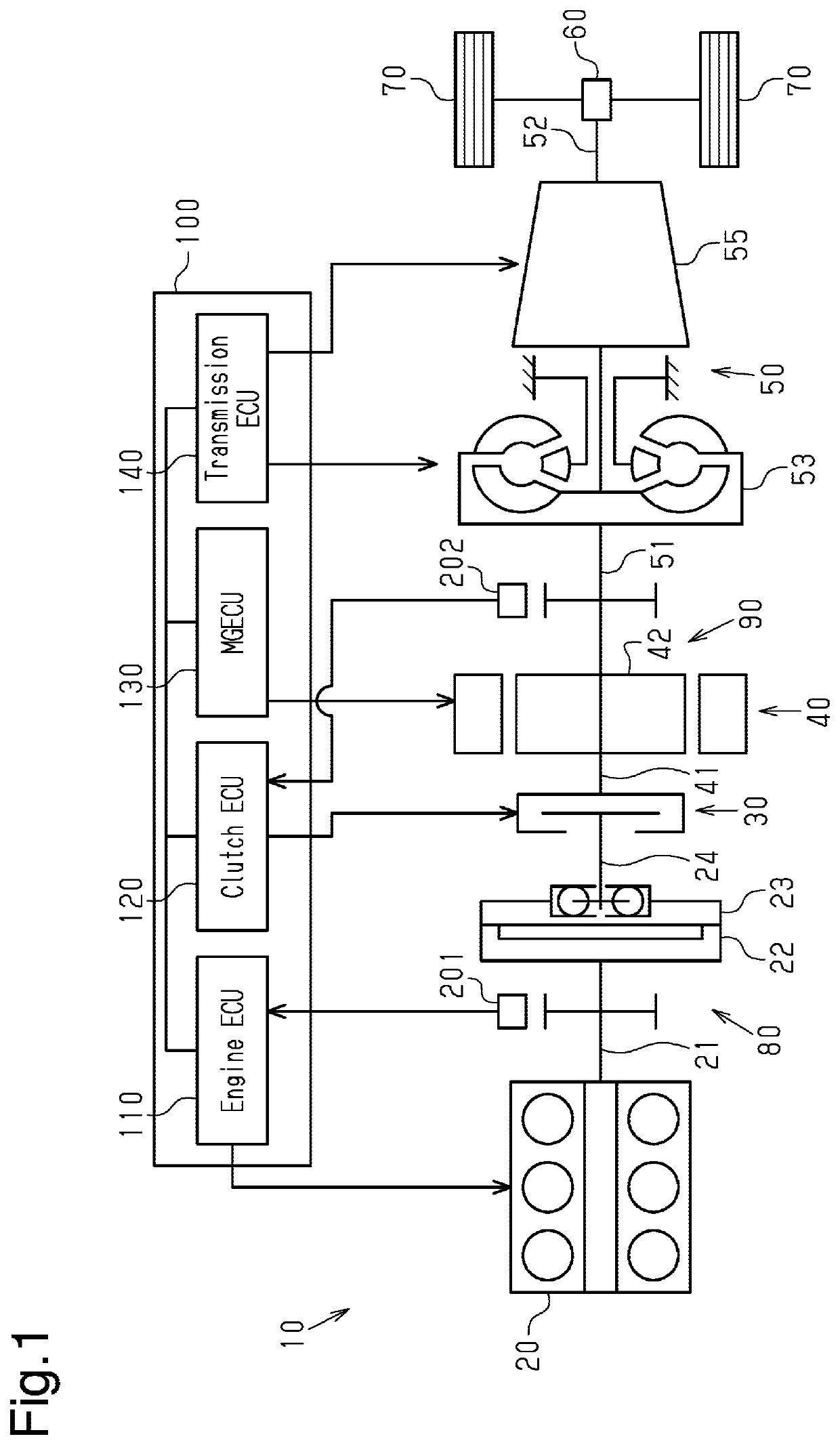
[0034]As shown in FIG. 1, the hybrid system 10 includes an internal combustion engine 20, which is a drive source of the vehicle. The internal combustion engine 20 has multiple cylinders and burns fuel supplied to the cylinders to rotate a crankshaft 21.

[0035]The internal combustion engine 20 includes a substantially disk-shaped flywheel 22 attached to an end of the crankshaft 21. The flywheel 22 is an inertial body having an appropriate weight and stabilizes the rotation speed of the internal combustion engine 20 to smooth rotation of the crankshaft 21.

[0036]A substantially disk-shaped torsional damper 23 is attached to the flywheel 22. The torsional damper 23 absorbs torsion in the rotation direction of the crankshaft 21, thereby reduci...

second embodiment

[0089]A balance control performed by a controller 100 according to a second embodiment of the present disclosure will now be described with reference to FIGS. 6 and 7. In the second embodiment, like or the same reference numerals are given to those components that are like or the same as the corresponding components of the first embodiment. Specific description of these components is omitted or simplified.

[0090]In the second embodiment, the clutch ECU 120 stores in advance the position of the engine-side center of gravity GE, which is the center of gravity of the engine-side rotating body 80 in relation to the reference position of the crankshaft 21. The clutch ECU 120 calculates the rotational position of the engine-side center of gravity GE from the information on the rotational position of the crankshaft 21 in relation to the reference position of the crankshaft 21, which has been detected by the crank angle sensor 201, and the position of the engine-side center of gravity GE in ...


PUM


Abstract

A controller for a hybrid system is provided. A clutch is disposed between a crankshaft and a drive shaft of an electric motor. An engine-side rotating body rotates integrally with the crankshaft. A motor-side rotating body rotates integrally with the drive shaft. The controller performs balance control. In the balance control, the controller causes the engine-side rotating body and the motor-side rotating body to rotate relative to each other by bringing the clutch into the slipping state. Thereafter, the controller switches the clutch to the engaged state such that the position of the center of gravity of the engine-side rotating body and the position of the center of gravity of the motor-side rotating body are farther from each other in the circumferential direction than before bringing the clutch into the slipping state.

Description

BACKGROUND1. Field[0001]The present disclosure relates to a controller and a control method for a hybrid system.2. Description of Related Art[0002]Japanese Laid-Open Patent Publication No. 2011-213310 discloses a hybrid vehicle in which the crankshaft of the internal combustion engine and the drive shaft of the electric motor are connected to each other via a clutch. The clutch is switched among an engaged state, a slipping state, and a disengaged state. When the clutch is in the engaged state, rotation torque can be transmitted between the crankshaft of the internal combustion engine and the drive shaft of the electric motor, and the crankshaft and the drive shaft rotate integrally. When the clutch is in the slipping state, rotation torque can be transmitted between the crankshaft of the internal combustion engine and the drive shaft of the electric motor, while the crankshaft and the drive shaft rotate relative to each other to some extent. When the clutch is in the disengaged sta...

Claims


Application Information

Patent Timeline
Patent Type & Authority Patents(United States)
IPC IPC(8): B60K6/387B60W20/40H02K7/04B60W10/02B60K6/26
CPCB60K6/387B60W10/026B60W20/40H02K7/04B60K2006/262B60W10/02B60W10/06B60W10/08B60W2510/0638B60W2510/0685B60W2540/10B60W2710/021F16D48/066B60K6/48B60K2006/268B60K2006/4825B60W30/20B60W2030/203H02K7/108Y02T10/62Y02T10/72
Inventor INAGAWA, TOMOKAZU
Owner TOYOTA JIDOSHA KK
Why Eureka
Try Eureka