

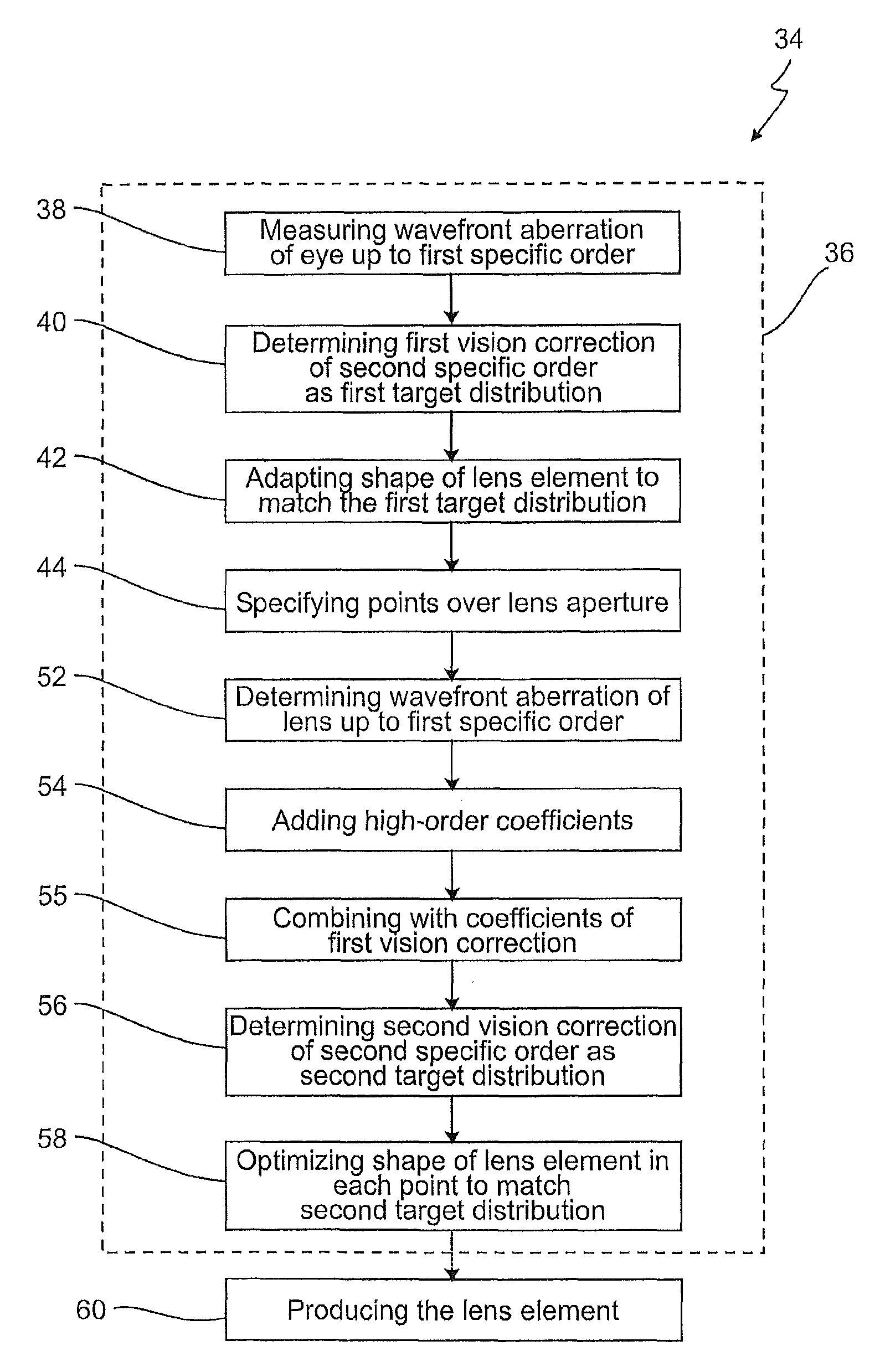
Method for optimizing a spectacle lens for the wavefront aberrations of an eye and lens
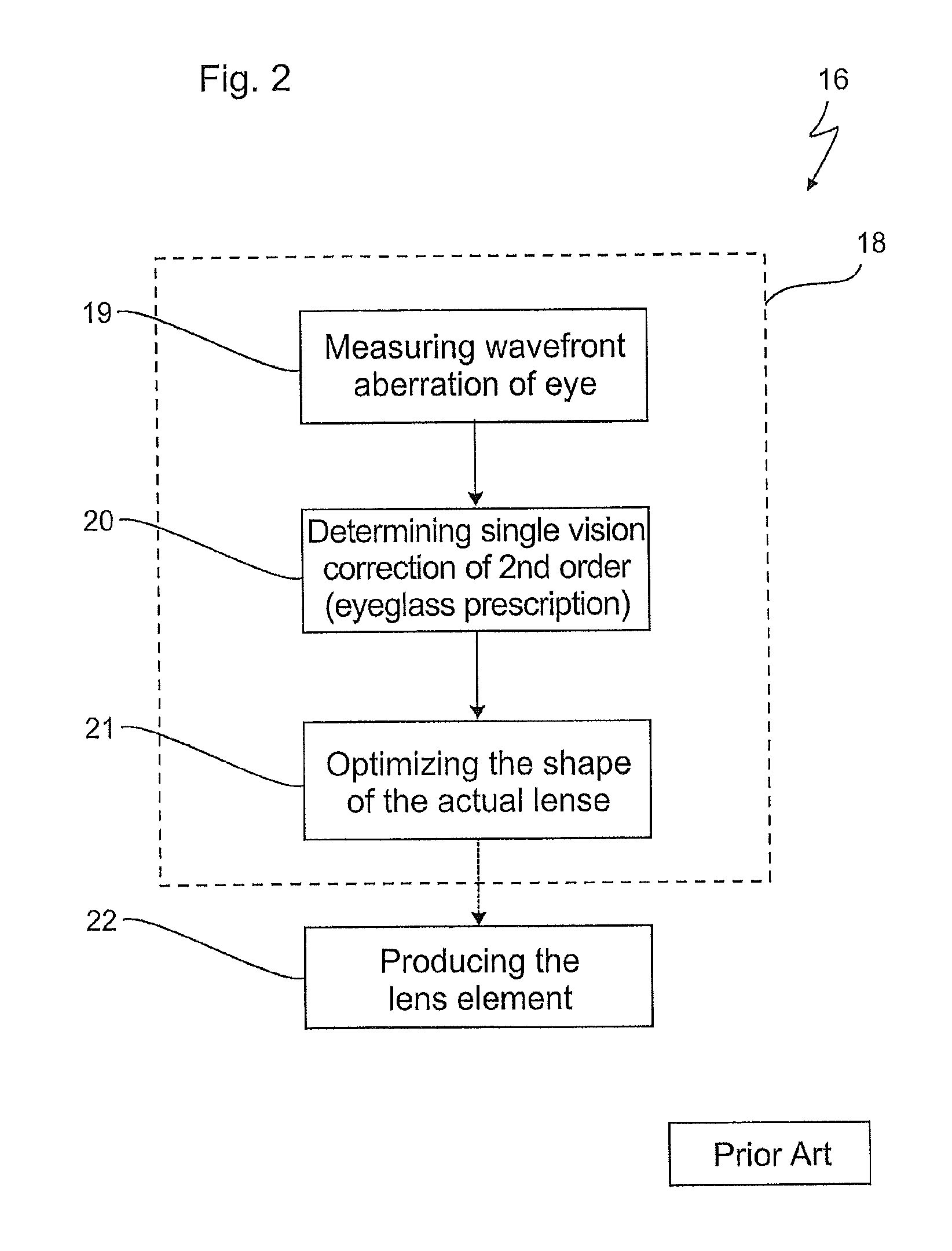
a wavefront aberration and lens technology, applied in the field of optimizing the wavefront aberration of the eye and lens, can solve the problems of limiting the visual performance, degrading the vision quality, and the eye examination procedure of traditional eyeglass prescriptions, so as to improve the visual performance, maximize the vision quality, and improve the visual performance
- Summary
- Abstract
- Description
- Claims
- Application Information
AI Technical Summary
Benefits of technology
Problems solved by technology
Method used
Image

Examples
Embodiment Construction
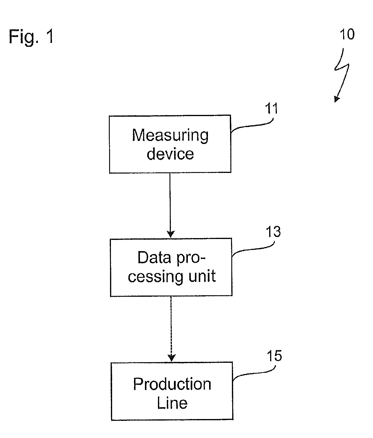
[0059]Referring to FIG. 1, a system 10 for carrying out the methods according to the current invention is shown. The system 10 may be used for designing an ophthalmic lens element or for designing and producing an ophthalmic lens element.
[0060]The system 10 comprises a measuring device 11 used for determining a wavefront aberration of an eye of a person for whom an eyeglass is to be produced. The measuring device may be a commonly known wavefront sensor or aberrometer, such as an wavefront sensor according to Shack-Hartmann.
[0061]Data obtained by the measuring device is then transferred into a data processing unit 13 which is adapted to conduct a method for a designing an ophthalmic lens element according to the current invention, for example by applying a computer program product according to the current invention. Generally, the data processing unit 13 may be a commonly known computer system.
[0062]The measuring device 11 and the data processing unit 13 may be directly connected vi...
PUM
 Abstract
Description
Claims
Application Information