Modular lighted floor mat for use beneath equipment

Active Publication Date: 2012-06-26
OLSON TIMOTHY ANDREW
View PDF12 Cites 26 Cited by
  • Summary
  • Abstract
  • Description
  • Claims
  • Application Information

AI Technical Summary

Benefits of technology

[0012]Still yet another object of the present invention is to provide a new modular lighted floor mat for use beneath equipment that is strong enough to withstand either equipment or the user resting on top thereof.
[0013]Even still another object of the present invention is to provide a new modular lighted floor mat for use beneath equipment that eliminates the user having to fumble around using lamps or flashlights to light up the area beneath the equipment.

Problems solved by technology

While these devices fulfill their respective, particular objectives and requirements, the aforementioned patents do not disclose a new modular lighted floor mat for use beneath equipment.

Method used


Image

  • Modular lighted floor mat for use beneath equipment
  • Modular lighted floor mat for use beneath equipment
  • Modular lighted floor mat for use beneath equipment

Examples


Embodiment Construction

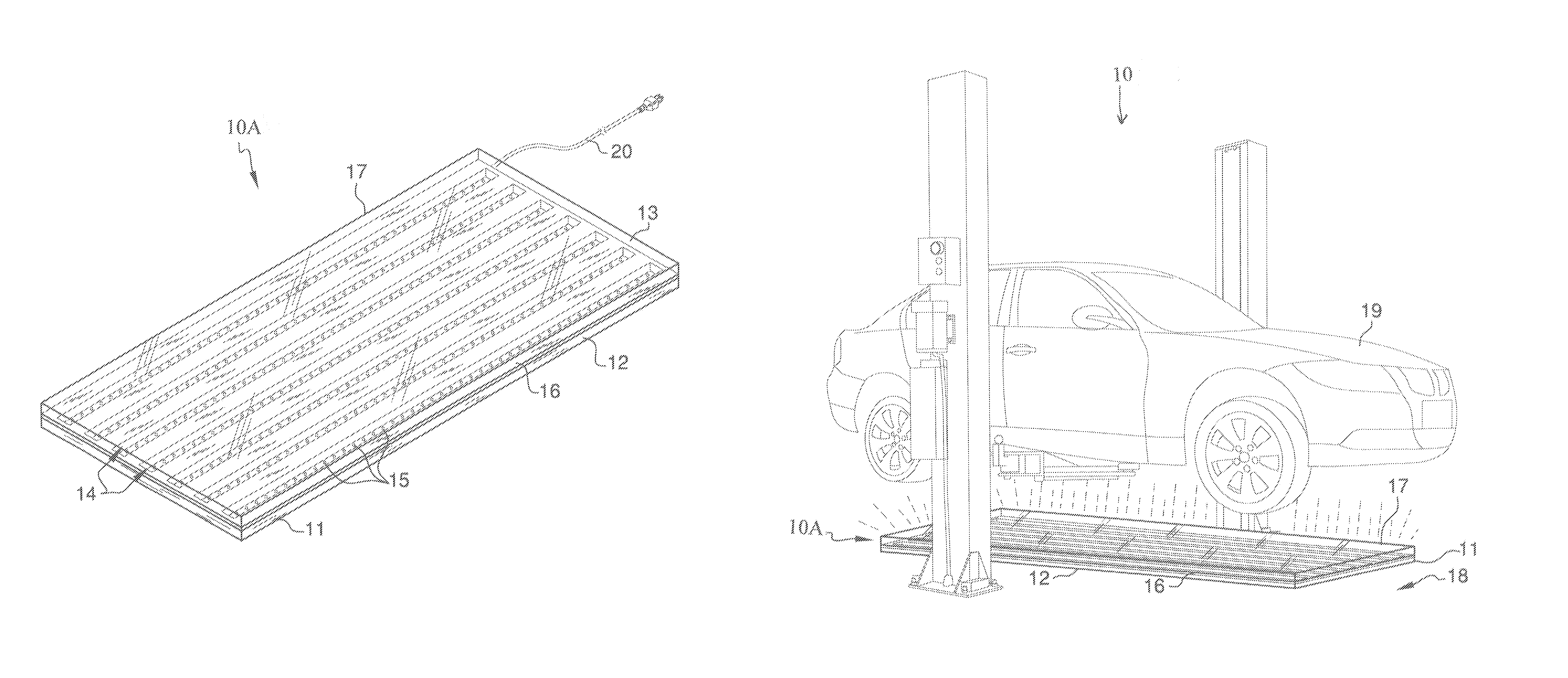
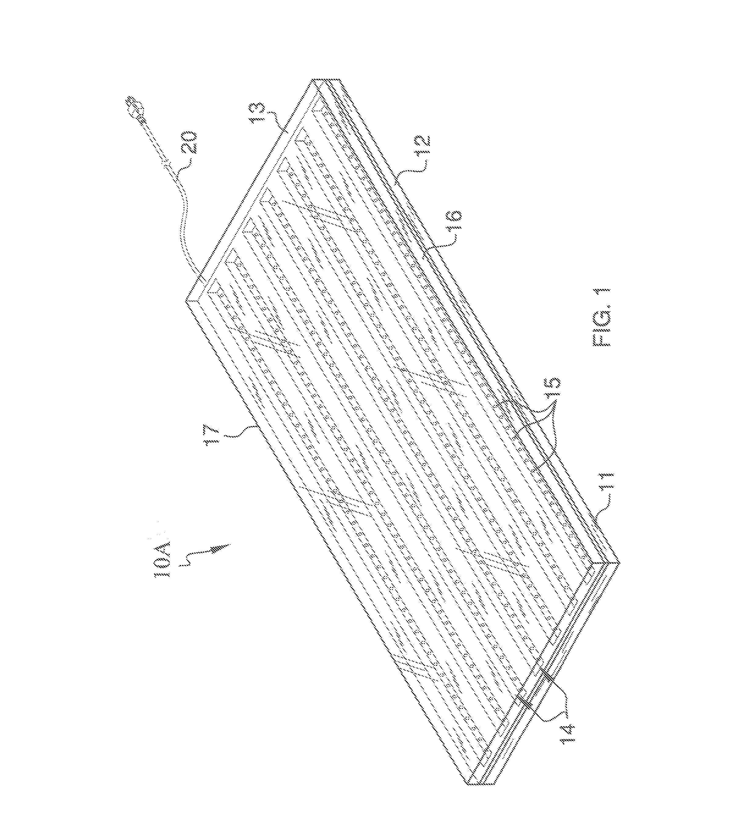
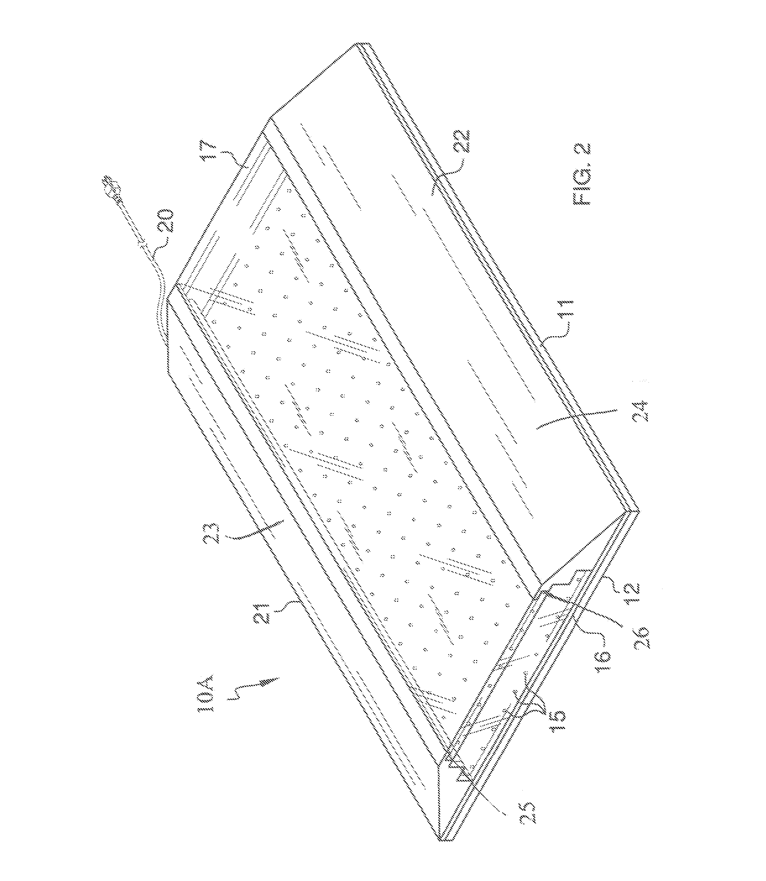
[0019]With reference now to the drawings, and in particular to FIGS. 1 through 3 thereof, a new modular lighted floor mat for use beneath equipment embodying the principles and concepts of the present invention and generally designated by the reference numeral 10 will be described.

[0020]As best illustrated in FIGS. 1 through 3, the modular lighted floor mat for use beneath equipment 10 generally comprises a lighted floor mat assembly 10A including a base member 11, light-emitting members 15, and a transparent load-bearing cover 17 being disposed over the light-emitting members 15 and the base member 11 and being capable of withstanding substantial weights and also being impervious to chemicals. The base member 11 is a planar material 12 having a thickness and a topside 13. One embodiment includes the light-emitting members 15 being spaced about and embedded in the topside 13 of the base member 11. Another embodiment includes the lighted floor mat assembly 10A having light reflective...


PUM


Abstract

A modular lighted floor mat for use beneath equipment for providing hands-free light necessary to work on the equipment. The modular lighted floor mat for use beneath equipment includes a lighted floor mat assembly including a base member, light-emitting members, and a transparent load-bearing cover being disposed over the light-emitting members and the base member and being capable of withstanding substantial weights and also being impervious to chemicals.

Description

BACKGROUND OF THE INVENTION[0001]1. Field of the Invention[0002]The present invention relates to floor mats and more particularly pertains to a new modular lighted floor mat for use beneath equipment for providing hands-free light necessary to work on the equipment.[0003]2. Description of the Prior Art[0004]The use of floor mats is known in the prior art. More specifically, floor mats heretofore devised and utilized are known to consist basically of familiar, expected and obvious structural configurations, notwithstanding the myriad of designs encompassed by the crowded prior art which have been developed for the fulfillment of countless objectives and requirements.[0005]The prior art includes a lighted floor mat system which has a mat with first and second portions and also including a light source being protectively disposed under the first portion with the first portion being designed to represent a logo with the light source shining through the logo and with the light source bei...

Claims


Application Information

Patent Timeline
IPC IPC(8): F21V33/00B25H5/00
CPCB25H5/00F21V33/00F21Y2105/00F21W2131/40
Inventor OLSON, TIMOTHY ANDREW
Owner OLSON TIMOTHY ANDREW
Why Eureka
Try Eureka