Fluorine cell

Inactive Publication Date: 2009-01-27
THE BOC GRP PLC
View PDF9 Cites 0 Cited by
  • Summary
  • Abstract
  • Description
  • Claims
  • Application Information

AI Technical Summary

Benefits of technology

[0005]It is an object of the present invention to provide a fluorine cell construction where significant areas of polymeric sealing members exposed to direct contact with fluorine are eliminated or minimised.
[0006]It is a further object of the present invention to provide a fluorine cell construction having a very high degree of integrity against fluorine leaks.

Problems solved by technology

However, due to the high currents which are inherent in fluorine generation by electrolysis a considerable amount of heat is generated by resistance heating, this condition often being exacerbated by poor electrical connection between the stud and carbon anode which is generally used.
The effect of this heating can be to cause a runaway chemical reaction between the plastics seal material and the fluorine with which it is in direct contact and which may result in a fluorine leak.
In extreme cases even the stud metal may itself burn in the fluorine gas stream in the resulting leak causing a so-called “stud fire”.
However, even in this construction, whilst an improvement on earlier constructions, the sealing gasket is still directly contacted by the fluorine gas and is still susceptible to attack especially when there is an unexpected temperature rise for any reason.

Method used


Image

  • Fluorine cell
  • Fluorine cell
  • Fluorine cell

Examples


Embodiment Construction

[0026]Referring now to the drawings and where the same features are denoted by common reference numerals.

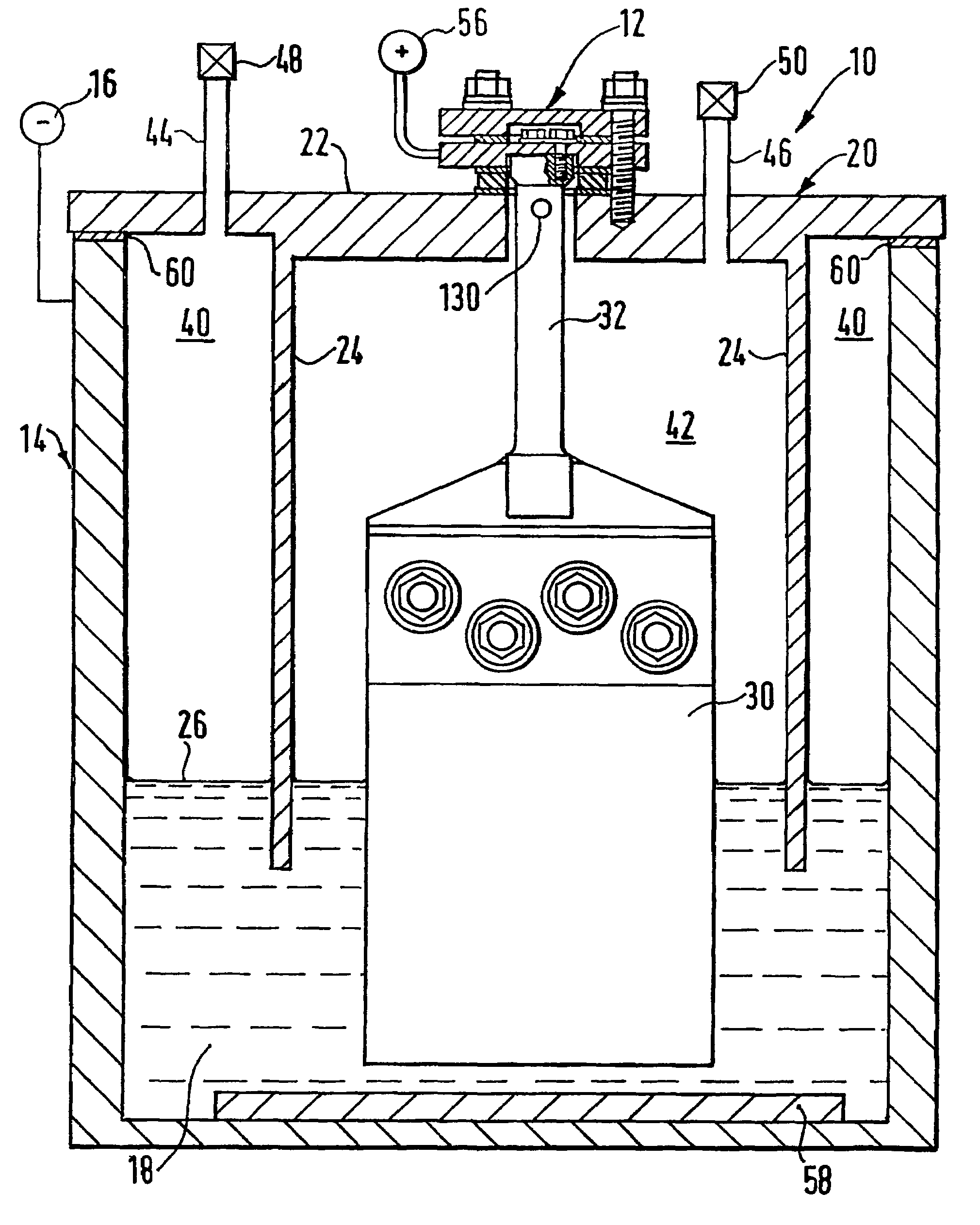
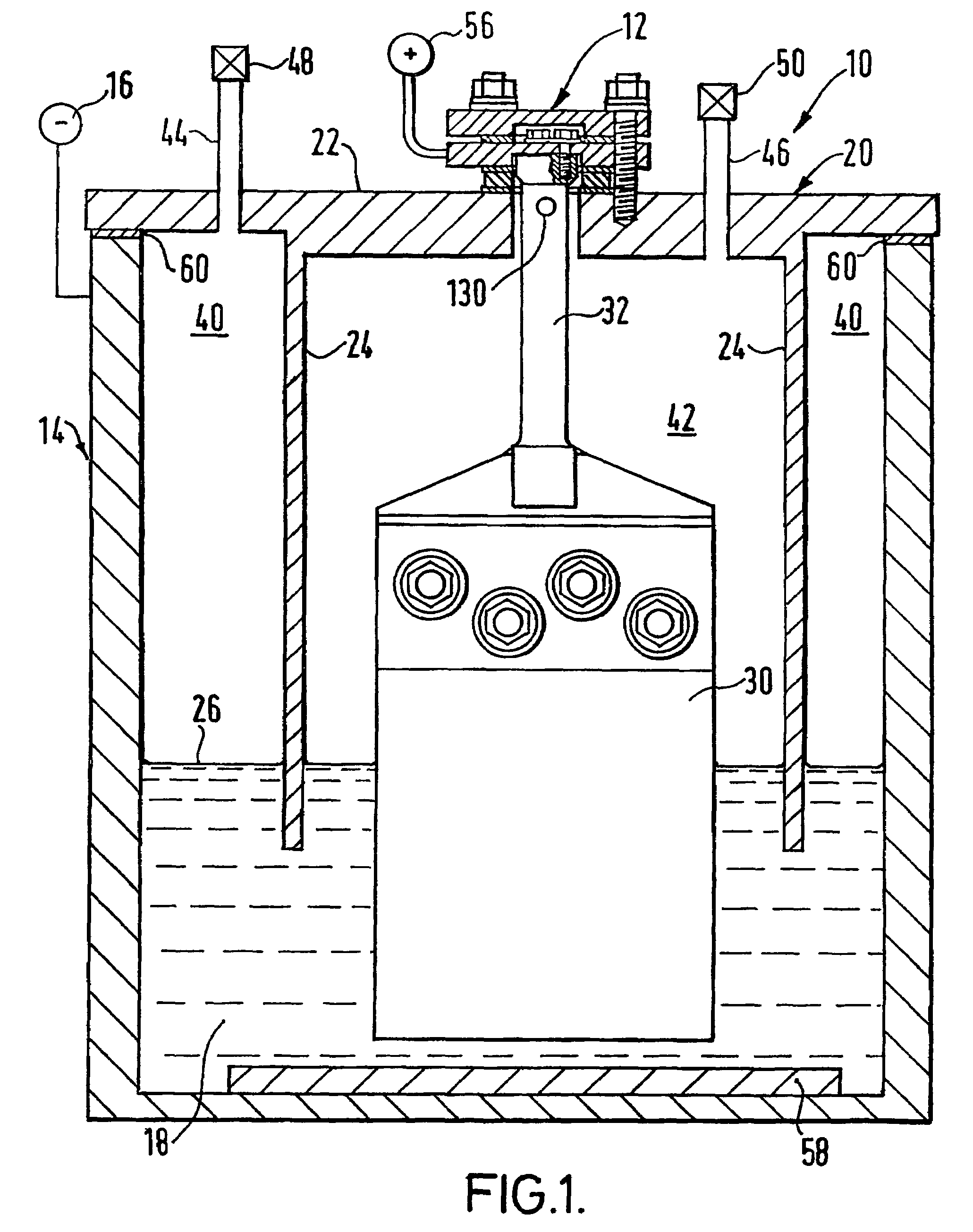
[0027]FIG. 1 shows an elevation in part cross section of a schematic electrolytic fluorine generating cell 10 having an anode sealing arrangement 12 according to the present invention. Most of the cell is conventional and is only shown and described to place the anode sealing arrangement of the present invention in context.

[0028]The cell 10 includes an outer cell vessel 14 which also forms the cathode 16 and contains the electrolyte 18; a skirt member 20 which comprises a generally horizontal top plate 22 and a depending gas separating skirt member 24 which extends below the surface 26 of the electrolyte 18 and completely encircles an anode 30 and anode connection member 32; and, an anode sealing arrangement 12, in this case according to the present invention. The construction of the cell forms two separate compartments 40, 42, each closed at the lower end by the electrolyte surf...


PUM

PropertyMeasurementUnit
Volumeaaaaaaaaaa

Abstract

An arrangement for installing and sealing an anode within a fluorine generating electrolytic cell is described, the arrangement comprising: an anode connection member, said anode connection member (32) passing through an aperture (70) in a skirt wall (20) and being in electrical connection with a skirt wall closure member (72) wherein the skirt wall closure member is sealingly engaged with said skirt wall and is electrically insulated therefrom.

Description

FIELD OF INVENTION[0001]The present invention relates to the construction of fluorine cells and particularly to the construction relating to the closing of the anode connection to the fluorine producing compartment in such a cell.BACKGROUND OF THE INVENTION[0002]Fluorine generating cells produce both gaseous fluorine and hydrogen by the electrolysis of hydrogen fluoride. Fluorine and hydrogen explosively recombine when they contact each other, therefore, it is necessary to keep them completely separate when generated during electrolysis. Fluorine cells are generally constructed such that the two gases are collected in two separate compartments above the surface level of the electrolyte. The compartments are often separated by means of a so-called skirt, the skirt often being part of and depending from an upper, generally horizontal wall of the cell, and extending into the electrolyte and surrounding the anode. However, the skirt must remain electrically neutral with respect to the a...

Claims


Application Information

Patent Timeline
IPC IPC(8): C25B9/02C25B9/00C25B1/24
CPCC25B9/02C25B1/245C25B9/63
Inventor HODGSON, GRAHAMDAWSON, ROBERT
Owner THE BOC GRP PLC
Why Eureka
Try Eureka