
Laser system employing harmonic generation

a laser beam and harmonic generation technology, applied in the field of laser systems, can solve the problem of difficult to use crystals with pulse durations less than five femtoseconds

Inactive Publication Date: 2012-06-26
BOARD OF TRUSTEES OPERATING MICHIGAN STATE UNIV
View PDF248 Cites 34 Cited by
  • Summary
  • Abstract
  • Description
  • Claims
  • Application Information

AI Technical Summary

Benefits of technology

"The present invention provides a laser system that can generate harmonics in a laser beam pulse. This is done by using a gaseous optical medium that creates third or greater harmonic generation in the pulse. The system also includes a controller that characterizes and compensates for distortions in the pulse. The invention can use multiple optical media arranged to cause cascading harmonic generations in a laser pulse, and can also use plasma to generate harmonics of the pulse. The invention eliminates the need for second harmonic generation crystals, reducing cost, complexity, and maintenance of the laser system. The invention is also advantageous for pulse durations less than five femtoseconds and can achieve useful harmonic generation at wavelengths that are otherwise difficult to obtain."

Problems solved by technology

By way of contrast, it is very difficult to use crystals with pulse durations less than five femtoseconds due to the very broad pulse bandwidth.

Method used


Image

  • Laser system employing harmonic generation
  • Laser system employing harmonic generation
  • Laser system employing harmonic generation

Examples


Embodiment Construction

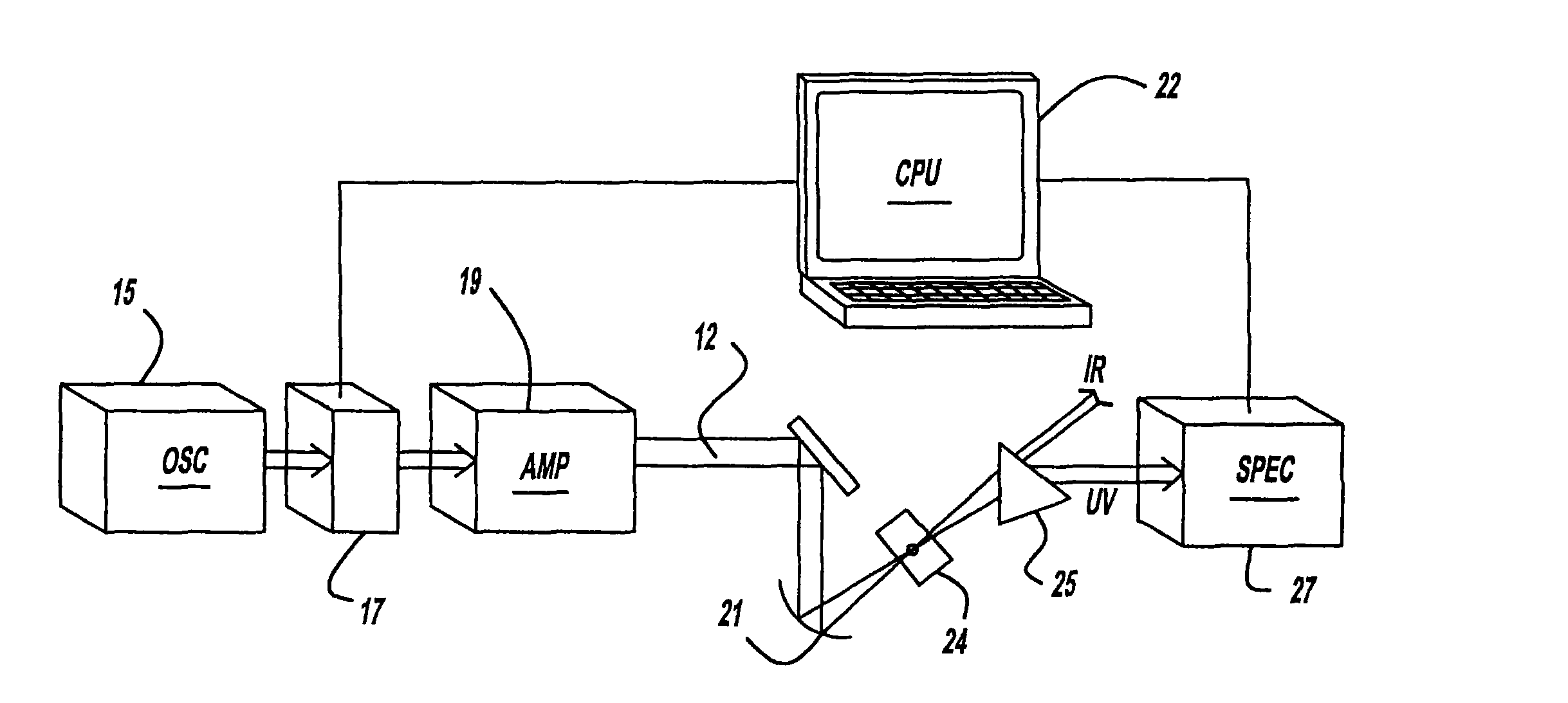
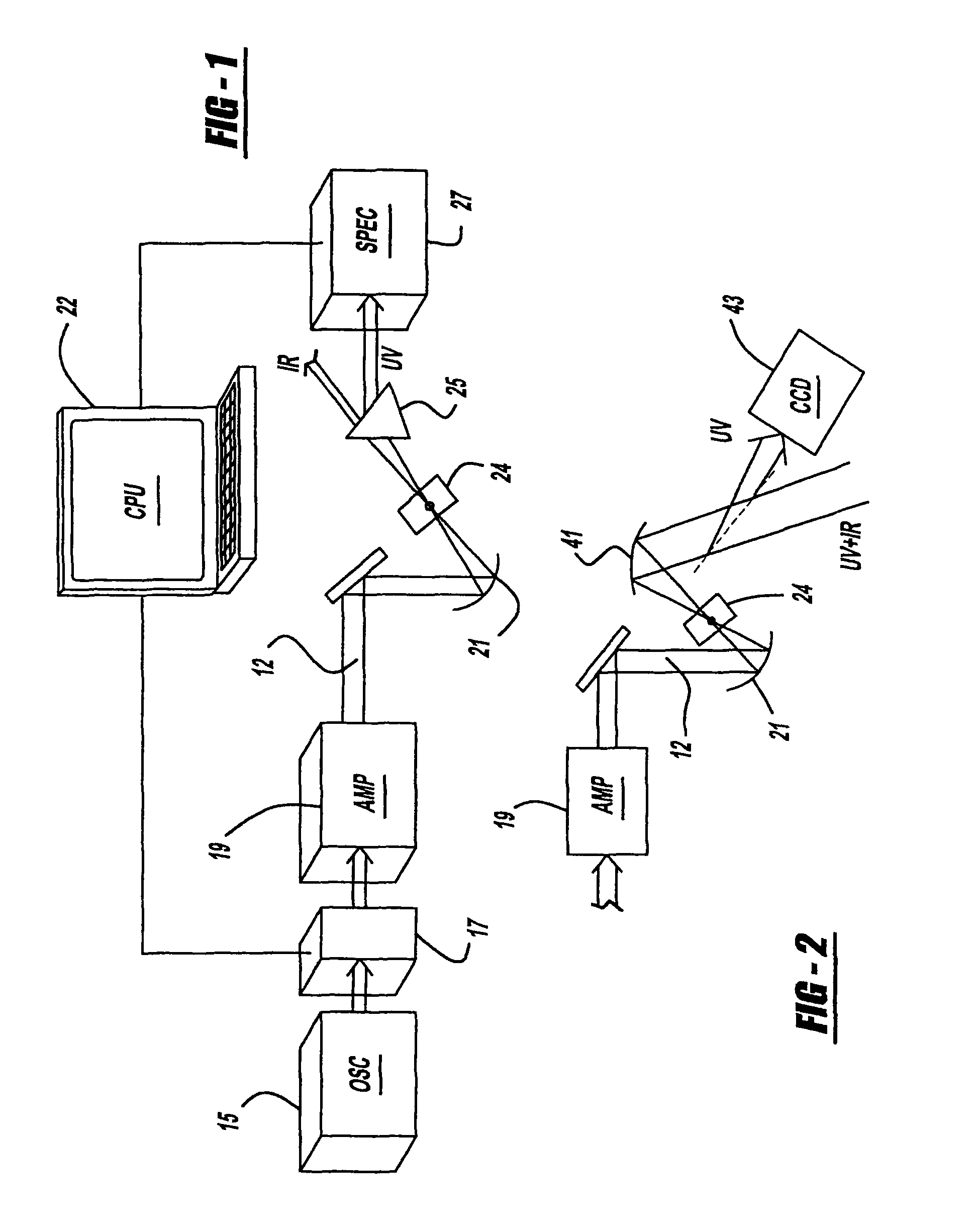
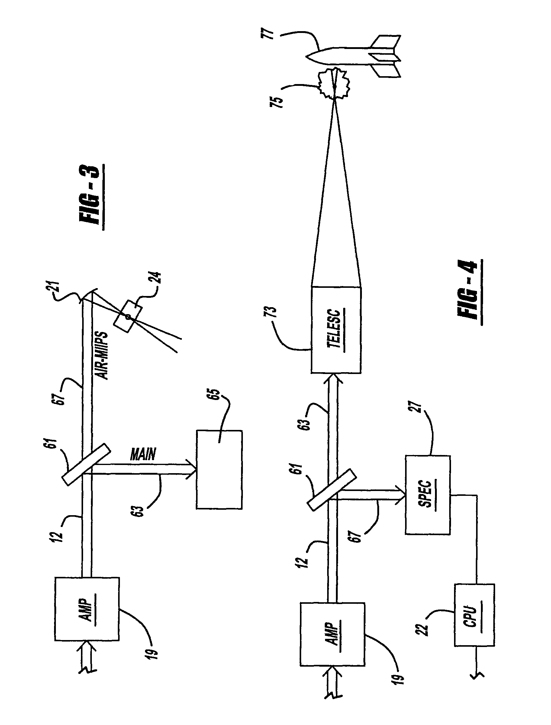
[0021]The present invention laser system preferably employs a noninterferometric single beam method for automated characterization and compression of amplified ultrashort femtosecond pulses that takes advantage of third order nonlinear processes in a gas, such as air. The method compensates high-order phase distortions based on Multiphoton Intrapulse Interference Phase Scan (hereinafter “MIIPS”). The accurate measurement of the spectral phase in femtosecond laser pulses is paramount to the use of phase-modulated laser pulses for femtochemistry, control of chemical reactions, and optical communications. Multiphoton Intrapulse Interference Phase Scan takes advantage of the influence that phase modulation has on the intensity of nonlinear optical processes. The MIIPS equipment and method are disclosed in U.S. Patent Publication No. 2006 / 0056468 entitled “Control System and Apparatus for Use with Ultra-Fast Laser,” which was invented by M. Dantus, et al., and published on Mar. 16, 2006;...


PUM


Abstract

A laser system provides harmonic generation in a laser beam pulse. In another aspect of the present invention, a laser operably remits a laser pulse, a gaseous optical medium operably creates third or greater harmonic generation in the pulse, and a controller characterizes and compensates for distortions in the pulse. A further aspect of the present invention employs multiple optical media arranged to cause cascading harmonic generations in a laser pulse.

Description

CROSS REFERENCE TO RELATED APPLICATION[0001]This application is a Continuation of PCT / US2007 / 024171, filed Nov. 16, 2007, which claims priority to U.S. Provisional Patent Application Ser. No. 60 / 859,421, filed Nov. 16, 2006, which are both incorporated by reference herein.[0002]This application is also a Continuation-In-Part of U.S. patent application Ser. No. 10 / 791,377, filed Mar. 2, 2004, which is a Continuation-In-Part of U.S. patent application Ser. No. 10 / 265,211, filed Oct. 4, 2002, which is a Continuation-In-Part of International Application No. PCT / US2002 / 02548, filed Jan. 28, 2002, which claims priority to U.S. Provisional Patent Application Ser. No. 60 / 265,133, filed Jan. 30, 2001. All of these applications are incorporated by reference herein.STATEMENT OF GOVERNMENT INTEREST[0003]A portion of this invention was made with U.S. Government support under Contract No. CHE-0421047 awarded by the National Science Foundation. The U.S. Government may have certain rights in this i...

Claims


Application Information

Patent Timeline
Patent Type & Authority Patents(United States)
IPC IPC(8): H01S3/10
CPCH01S3/0057H01S3/0092H01S3/10053H01S3/2308G01B9/0209G01B9/02091G01B9/02067G01B9/02014
Inventor DANTUS, MARCOSHARRIS, DON AHMASILOZOVOY, VADIM V.
Owner BOARD OF TRUSTEES OPERATING MICHIGAN STATE UNIV
Learn More