Pneumatic tire with tread having inside and outside circumferential sipes

a technology of pneumatic tires and circumferential sipes, which is applied in the field of pneumatic tires, can solve the problems of insufficient edge effect so as to achieve the effect of handling performance, inability to ensure stiffness of inside blocks, and inability to ensure stiffness of outside blocks

Active Publication Date: 2012-07-03
BRIDGESTONE CORP
View PDF20 Cites 0 Cited by
  • Summary
  • Abstract
  • Description
  • Claims
  • Application Information

AI Technical Summary

Benefits of technology

[0007]Therefore, it is an object of the present inventions to provide a pneumatic tire that can improve a handling performance, especially, a startup accelerating performance, a braking performance and a cornering performance.
[0009]In this manner, since the outside circumferential sipes extend along the tire radial direction in zigzag patterns, zigzag patterns along the tire radial direction in the outside circumferential sipes are engaged each other and thereby strength against lateral forces while cornering is increased. As a result, stiffness reduction of the outside blocks can be restrained. Since deformations of the outside blocks can be restrained and then the edge effect can be improved, a handling performance, especially, a cornering performance can be improved regardless of road surface conditions such as dry roads, wet roads or snow / ice covered roads.
[0010]Here, it is preferable that the circumferential sipes extend along the tire circumferential direction in zigzag patterns. According to this configuration, since the circumferential sipes extend along the tire circumferential direction in zigzag patterns, strength against forward and backward forces at starting and braking can be increased and then the edge effect can be improved. As a result, a handling performance, especially, a startup accelerating performance and a braking performance can be improved.
[0011]Here, it is preferable that lateral sipes extending along the tread width direction are provided in the blocks. According to this configuration, since the lateral sipes are provided in the blocks, the edge effect can be improved at starting and braking. As a result, a handling performance, especially, a startup accelerating performance and a braking performance can be improved.
[0012]Here, it is preferable that, among the lateral sipes, inside lateral sipes, which are positioned inside the tire equatorial plane under being equipped onto a vehicle, extend along the tire radial direction in zigzag patterns, and outside lateral sipes, which are positioned outside the tire equatorial plane under being equipped onto a vehicle, extend straight along the tire radial direction. According to this configuration, since the inside lateral sipes extend along the tire radial direction in zigzag patterns, zigzags along the tire radial direction in the inside lateral sipes are engaged each other and thereby strength against loads at starting and braking is increased. As a result, stiffness reduction of the inside blocks can be restrained. Since, deformations of the inside blocks can be restrained and then the edge effect can be improved, a handling performance, especially, a startup accelerating performance and a braking performance can be improved regardless of road surface conditions such as dry roads, wet roads or snow / ice covered roads.
[0013]Here, it is preferable that the lateral sipes extend along the tread width direction in zigzag patterns. According to this configuration, since the lateral sipes extend along the tread width direction in zigzag patterns, strength against cornering lateral forces can be increased and then the edge effect can be improved. As a result, a handling performance, especially, a cornering performance can be improved.

Problems solved by technology

However, according to a conventional pneumatic tire with circumferential sipes formed in its blocks in addition to lateral sipes, large loads apply to inside blocks under being equipped onto a vehicle at starting and braking, and thereby stiffness of the inside blocks cannot be ensured.
In addition, large loads apply to outside blocks while high-speed cornering and while cornering in tight corners, and thereby stiffness of the outside blocks cannot be ensured.
Thus, the edge effect cannot be exerted sufficiently due to large deformations of the inside or outside blocks, and thereby a handling performance (especially, a startup accelerating performance, a braking performance and a cornering performance) on dry roads and snow or ice covered roads is decreased.

Method used


Image

  • Pneumatic tire with tread having inside and outside circumferential sipes
  • Pneumatic tire with tread having inside and outside circumferential sipes
  • Pneumatic tire with tread having inside and outside circumferential sipes

Examples


modified example 1

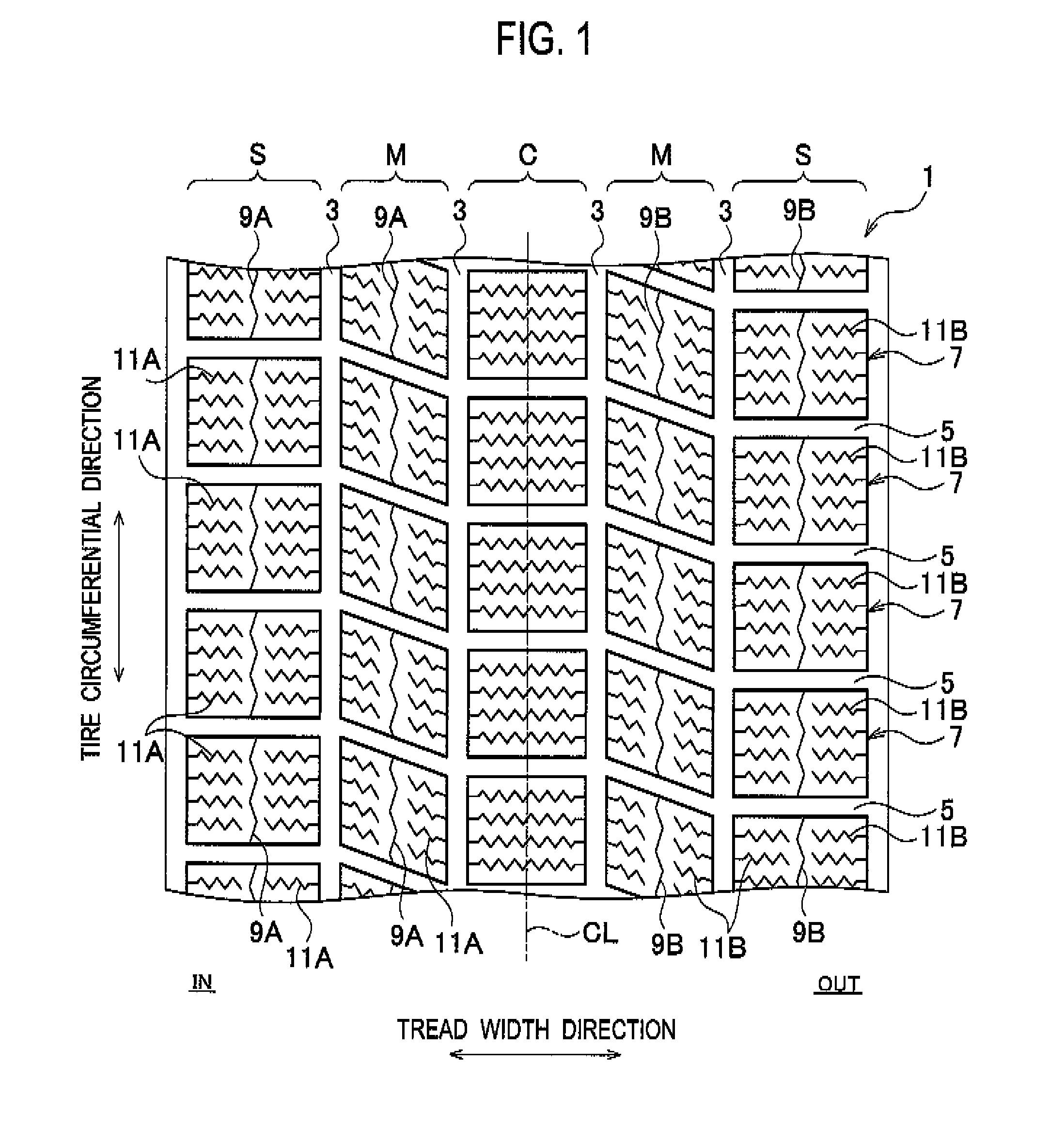
[0035]The circumferential sipes 9 (the inside circumferential sipes 9A and the outside circumferential sipes 9B) in the above-described embodiment extend along the tire circumferential direction in zigzag patterns. However, the circumferential sipes can be modified as described below. Note that different points from the pneumatic tire 1 in the above-described embodiment will be mainly explained hereinafter.

[0036]As shown in FIG. 6(a), the inside circumferential sipes 9A extend straight along the tire circumferential direction. Also in this case, the inside circumferential sipes 9A extend straight along the tire radial direction.

[0037]In addition, as shown in FIG. 6(b), the outside circumferential sipes 9B extend straight along the tire circumferential direction. Also in this case, the outside circumferential sipes 9B extend along the tire radial direction in zigzag patterns.

modified example 2

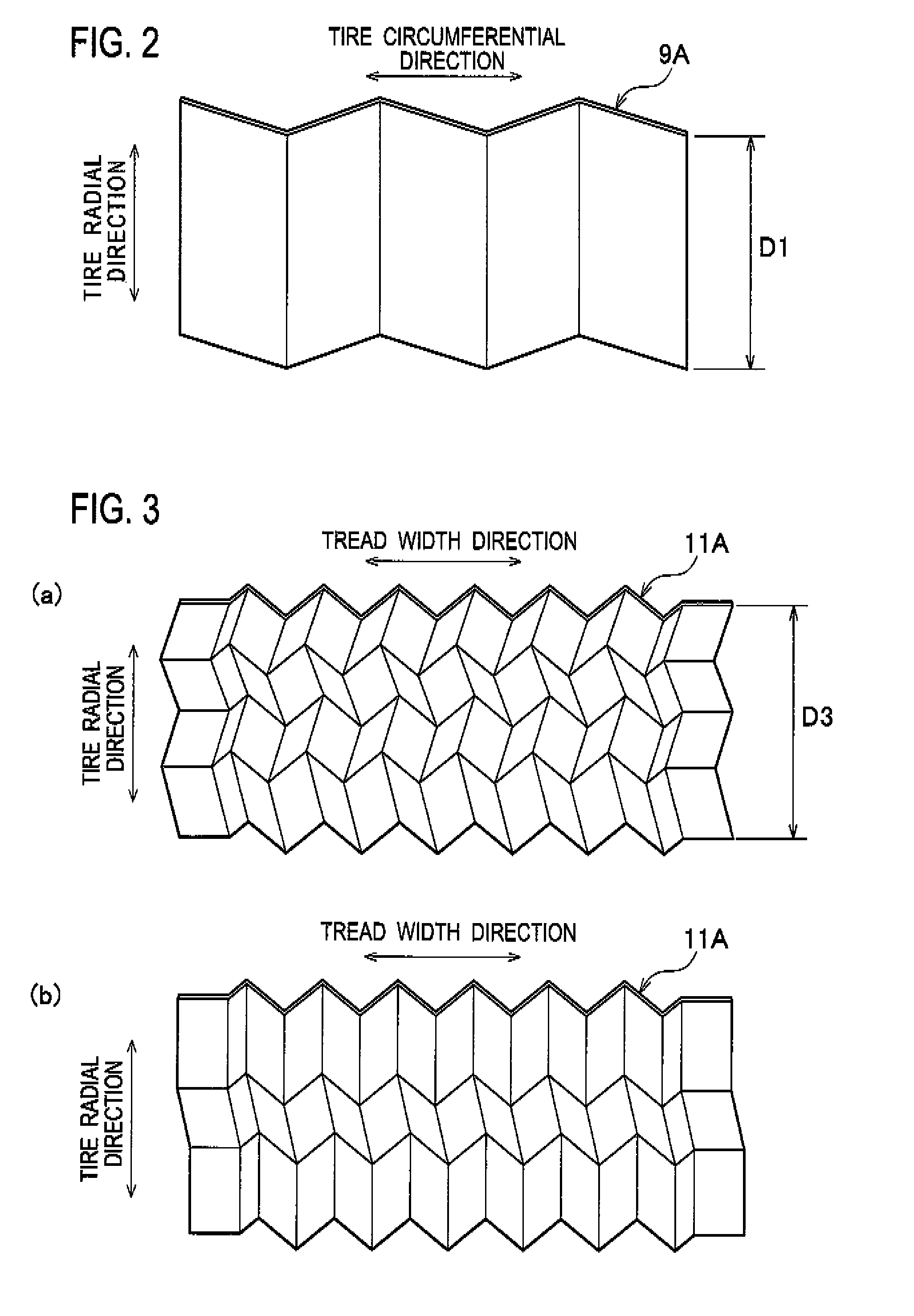
[0038]In addition, the present invention goes beyond the above modified embodiment. The lateral sipes 11 (the inside lateral sipes 11A and the outside lateral sipes 11B) in the above-described embodiment extend along the tire width direction in zigzag patterns. However, the lateral sipes can be modified as described below.

[0039]As shown in FIG. 7(a), the inside lateral sipes 11A extend straight along the tread width direction. Also in this case, the inside lateral sipes 11A extend along the tire radial direction in zigzag patterns.

[0040]In addition, as shown in FIG. 7(b), the outside lateral sipes 11B extend straight along the tread width direction. Also in this case, the outside lateral sipes 11B extend straight along the tire radial direction.

modified example 3

[0041]In addition, the present invention goes beyond the above modified embodiments and can be modified as described below.

[0042]In the above-described embodiment, all the inside lateral sipes 11A extend along the tire radial direction in zigzag patterns. However, the inside lateral sipes are not limited to this configuration. At least some of the inside lateral sipes 11A may extend along the tire radial direction in zigzag patterns.

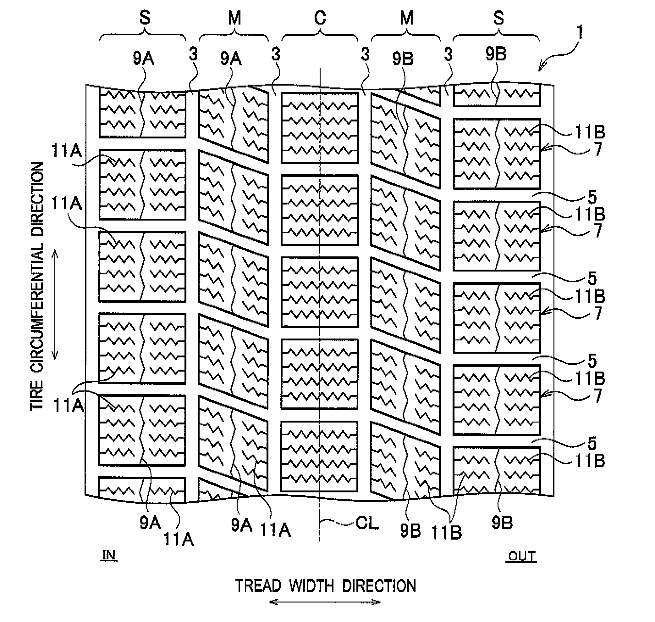
[0043]For example, as shown in FIG. 1, only the inside lateral sipes 11A in the blocks 7 located in tread shoulder areas S may extend along the tire radial direction in zigzag patterns. In addition, only the inside lateral sipes 11A in the blocks 7 located in tread middle areas M between a tread center area C and the tread shoulder areas S may extend along the tire radial direction in zigzag patterns.

[0044]In addition, in the above-described embodiment, all the outside circumferential sipes 9B extend along the tire radial direction in zigzag patterns. Ho...


PUM


Abstract

A pneumatic tire according to the present invention includes blocks on its tread which are segmented by plural circumferential grooves 3 extending along a tire circumferential direction and plural lateral grooves 5 extending along a tread width direction. Circumferential sipes extending along the tire circumferential direction are provided in the blocks. Inside circumferential sipes extend straight along a tire radial direction and outside circumferential sipes extend along the tire radial direction in zigzag patterns. According to the present invention, a handling performance, especially, a cornering performance can be improved regardless of road surface conditions.

Description

TECHNICAL FIELD[0001]The present inventions relate to a pneumatic tire having blocks on its tread which are segmented by plural circumferential grooves and plural lateral grooves.BACKGROUND ART[0002]Heretofore, various proposals have been made with respect to a pneumatic tire for improving a handling performance on snow or ice covered roads by increasing a gripping force (i.e. an edge effect). For example, in a Patent Document listed below, disclosed is a pneumatic tire in which lateral sipes extending along a tread width direction are provided on blocks segmented by circumferential grooves and lateral grooves.[0003]In this pneumatic tire, the edge effect can be exerted sufficiently at starting and braking, and thereby a handling performance (especially, a startup accelerating performance and a braking performance) is made improved. However, according to this pneumatic tire, friction between its tread and a road surface becomes small while cornering, and thereby sideslips may occur....

Claims


Application Information

Patent Timeline
Patent Type & Authority Patents(United States)
IPC IPC(8): B60C11/12
CPCB60C11/11B60C11/12B60C11/1218B60C2011/1213Y10S152/03Y10S152/902B60C5/00B60C11/00
Inventor KIWAKI, YUKIHIROWATABE, RYOICHI
Owner BRIDGESTONE CORP
Why Eureka
Try Eureka