Tissue retractor system

a retractor and tissue technology, applied in the field of tissue retractor systems, can solve the problems of increasing the risk of complications from surgery and longer recovery time, increasing the risk of complications, and reducing the range of motion of components, so as to reduce the size of the incision, and minimize the effect of the first incision siz

Inactive Publication Date: 2012-07-03
AESCULAP IMPLANT SYST
View PDF111 Cites 25 Cited by
  • Summary
  • Abstract
  • Description
  • Claims
  • Application Information

AI Technical Summary

Benefits of technology

[0006]In a fourth aspect of the invention, a tissue retractor system for maintaining and adjusting the size of an incision during a minimally invasive surgical procedure includes a retractor arm and a retractor blade. The retractor arm includes a top surface, a bottom surface opposite the top surface, and a slot that extends through the arm between the top surface and the bottom surface. The retractor blade is locked in the slot of the retractor arm by a locking mechanism. At least one of the slot and the retractor blade includes a contoured sidewall. The contoured sidewall allows insertion of the blade into the slot through the top surface of the arm and prevents the blade from completely exiting the slot through the bottom surface of the arm.
[0007]In a fifth aspect of the invention, a minimally-invasive learning procedure for inserting a spinal fixation rod is provided which allows a surgeon to gradually increase their proficiency and decrease the size of the incision that they make to insert the rod. In one version, the method includes the step of making a first incision through tissue and a second incision through tissue in proximity to the first incision. A dividable tube is inserted into the first incision. The dividable tube includes a pair of semi-cylindrical blades that form a generally cylindrical tube when mated together. A first rod receiving anchor is inserted through the dividable tube and driven into bone beneath the first incision. A second rod receiving anchor is driven into bone beneath the second incision. For the less experienced surgeon, the dividable tube blades may be spread apart from one another to widen the first incision prior to inserting the rod receiving anchor into the first incision. For the more experienced surgeon, the dividable tube blades may be kept in a closed condition during insertion of the anchor, thereby minimizing the size of the first incision. The spacing between the dividable tube blades, as well as the orientations of the blades, may be adjusted by the surgeon at any time during the procedure. The spacing between the blades is adjustable in small increments anywhere between a fully opened and fully closed condition to suit the surgeon's skill level. A spinal rod having a leading end is inserted through the dividable tube and into the first incision. The blades of the dividable tube may be spread apart at any spacing to provide additional room to manipulate the rod and insertion instrument between the tube blades. Once the spinal rod is inserted through the dividable tube, the spinal rod is turned so that the leading end of the rod is steered through one of the gaps between the blades. The leading end is turned subcutaneously toward the second rod receiving anchor and advanced until the leading end is received by a rod receiving slot in the second rod receiving anchor. The trailing end of the spinal rod is received in a rod receiving slot of the first rod receiving anchor. The spinal rod is then secured to the rod receiving anchors.

Problems solved by technology

Large incisions that strip muscle or damage delicate tissue lead to increased patient trauma, increased risk of complications from surgery and longer recovery times.
The components often have a limited range of motion, and only work with larger incisions.
Moreover, many retractor systems have large levers and other obstructions that limit operability and the ability to neatly arrange the instrumentation over the incision.
Often times, this limits the ability to move components smoothly to expand or retract the incision.
Furthermore, known systems fail to adequately support the vertical position of the blades in the incision, and keep the blade arms stabilized.
Based on all of these drawbacks, known retractor assemblies leave much to be desired in terms of operational flexibility, functionality, adaptability to different procedures, adaptability to different surgeon preferences, and other aspects.

Method used


Image

  • Tissue retractor system
  • Tissue retractor system
  • Tissue retractor system

Examples


Embodiment Construction

[0039]Although the invention is illustrated and described herein with reference to specific embodiments, the invention is not intended to be limited to the details shown. Rather, various modifications may be made in the details within the scope and range of equivalents of the claims and without departing from the invention.

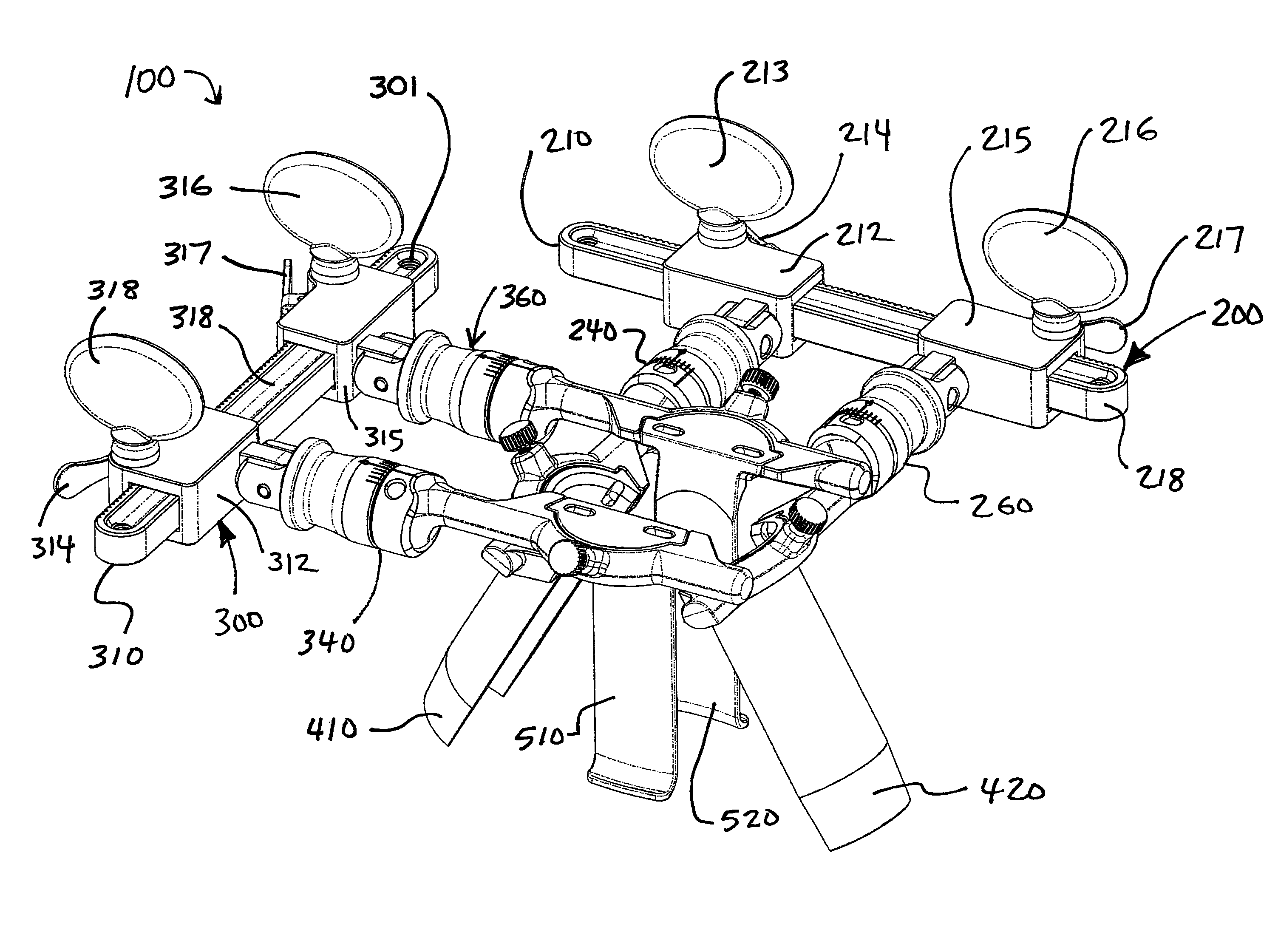
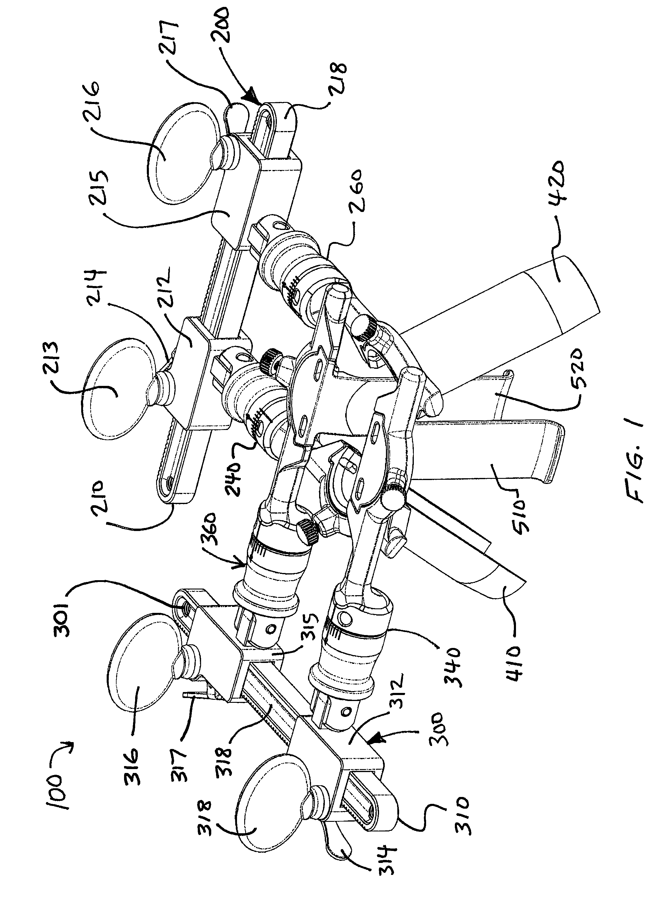
[0040]Referring now to FIG. 1, a retractor assembly or “mini-retractor”100 is shown in accordance with a first exemplary embodiment of the invention. Retractor assembly 100 includes a first retractor unit 200 and a second retractor unit 300 placed on top of the first retractor unit in a stacked or nested arrangement. The pair of retractor units cooperate with one another while working independently to control the size and shape of an incision. As will be explained in more detail below, first retractor unit 200 can be operated by itself within an incision, or accompanied by the second retractor unit 300 if deemed necessary by the surgeon. If operated alone, the fir...


PUM


Abstract

A tissue retractor system includes first and second arms extending from a support assembly, and third and fourth arms extending from a support mechanism. Each arm includes a proximal span, a distal span, and a blade support between the proximal span and distal span. The retractor system features retractor units that can be used independently or in a nested arrangement. The system also includes instruments for inserting a spinal rod. A method for implanting a spinal rod through an incision includes the steps of inserting the spinal rod through a dividable tube, turning the rod subcutaneously toward a rod receiving anchor and advancing the rod subcutaneously toward the rod receiving anchor.

Description

BACKGROUND OF THE INVENTION[0001]In surgical procedures that require incisions, it is desirable to establish a clear and unobstructed view of the operating field. Various instruments are available to hold an incision open and maintain muscles, organs, blood vessels and other tissue out of the field of view. The desire to establish a clear and unobstructed view of the operating field must be balanced with the need to minimize trauma to the patient. Large incisions that strip muscle or damage delicate tissue lead to increased patient trauma, increased risk of complications from surgery and longer recovery times.[0002]A number of retractor assemblies have been developed that hold open incisions, while limiting damage to tissue. These assemblies use long “blades” to hold open incisions. Many retractors are designed to be used in essentially one way, with a fixed arrangement of components. The components often have a limited range of motion, and only work with larger incisions. Moreover,...

Claims


Application Information

Patent Timeline
Patent Type & Authority Patents(United States)
IPC IPC(8): A61B1/32
CPCA61B17/0206A61B17/7083A61B17/7076A61B17/0218A61B17/7085
Inventor WING, CHARLESBEUTLER, WILLIAM J.MCMURRAY, WALTER J.BUSS, DONALD A.HUGHETT, JAMES DAVIDTOMPKINS, JEFFREY S.COLE, JEFFREY
Owner AESCULAP IMPLANT SYST
Why Eureka
Try Eureka