Welding aid for a spiral-wound filament

a spiral-wound filament and welding aid technology, which is applied in the manufacture of cold cathode, electrode system, electric discharge tube/lamp, etc., can solve the problems of reduced or inhomogeneous luminance, reduced temperature of the first 1-3 turns of incandescent filament, and non-optimal light distribution in the lamp, in particular in the headlamp, so as to improve luminance and light distribution, reduce temperature gradient, and prolong lamp life

Inactive Publication Date: 2012-07-03
OSRAM GMBH
View PDF12 Cites 0 Cited by
  • Summary
  • Abstract
  • Description
  • Claims
  • Application Information

AI Technical Summary

Benefits of technology

[0006]The object of the present invention is therefore to provide a welding aid and a lamp with such a welding aid and a method for attaching such a welding aid which improves the abovementioned disadvantages of the prior art.
[0008]Owing to this power-dependent scaling of the distance d between the welding aid and the incandescent filament body, it is firstly possible to minimize the distance d in the case of lamps with low wattages, as a result of which the component size can overall be reduced. Secondly, the optimized distance d makes it possible to reduce the temperature withdrawal, as a result of which the temperature gradient can be markedly reduced.
[0011]0.018≤dP≤0.06⁢mmWhas proven to be particularly advantageous. Such a scaling results in a very low temperature gradient and therefore brings about a homogeneous luminance, which in turn results in an improved light distribution in the headlamp. For example, it is thus possible to ensure a defined light / dark boundary if the lamp is intended to be used as a headlamp for the lower beam.
[0014]Advantageously, owing to the distance between the welding aid and the incandescent filament body which is scaled with the electrical power of the incandescent filament, the temperature gradient is reduced, and the luminance and the light distribution improved, as a result of which a longer life of the lamp is also achieved.

Problems solved by technology

One disadvantage with the use of welding aids, however, is the fact that the temperature of the first 1-3 turns of the incandescent filaments is reduced owing to the additional thermal capacities of the welding aid.
This results in a reduced or inhomogeneous luminance, which in turn results in a non-optimal light distribution in the lamp, in particular in the headlamp.
Furthermore, the tungsten transfer from the filament center to the filament ends is increased, which can result in turn-to-turn short circuits and ultimately in a reduced life of the lamp.

Method used


Image

  • Welding aid for a spiral-wound filament
  • Welding aid for a spiral-wound filament
  • Welding aid for a spiral-wound filament

Examples


Embodiment Construction

[0006]The object of the present invention is therefore to provide a welding aid and a lamp with such a welding aid and a method for attaching such a welding aid which improves the abovementioned disadvantages of the prior art.

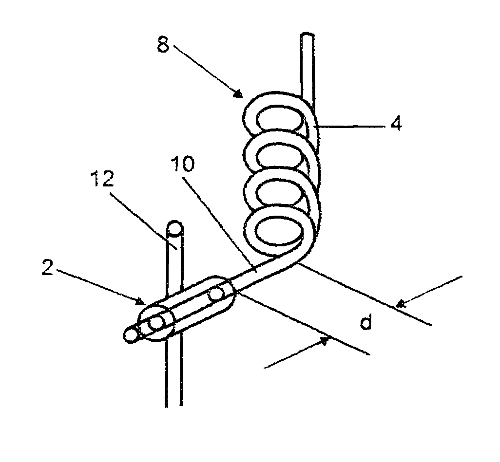
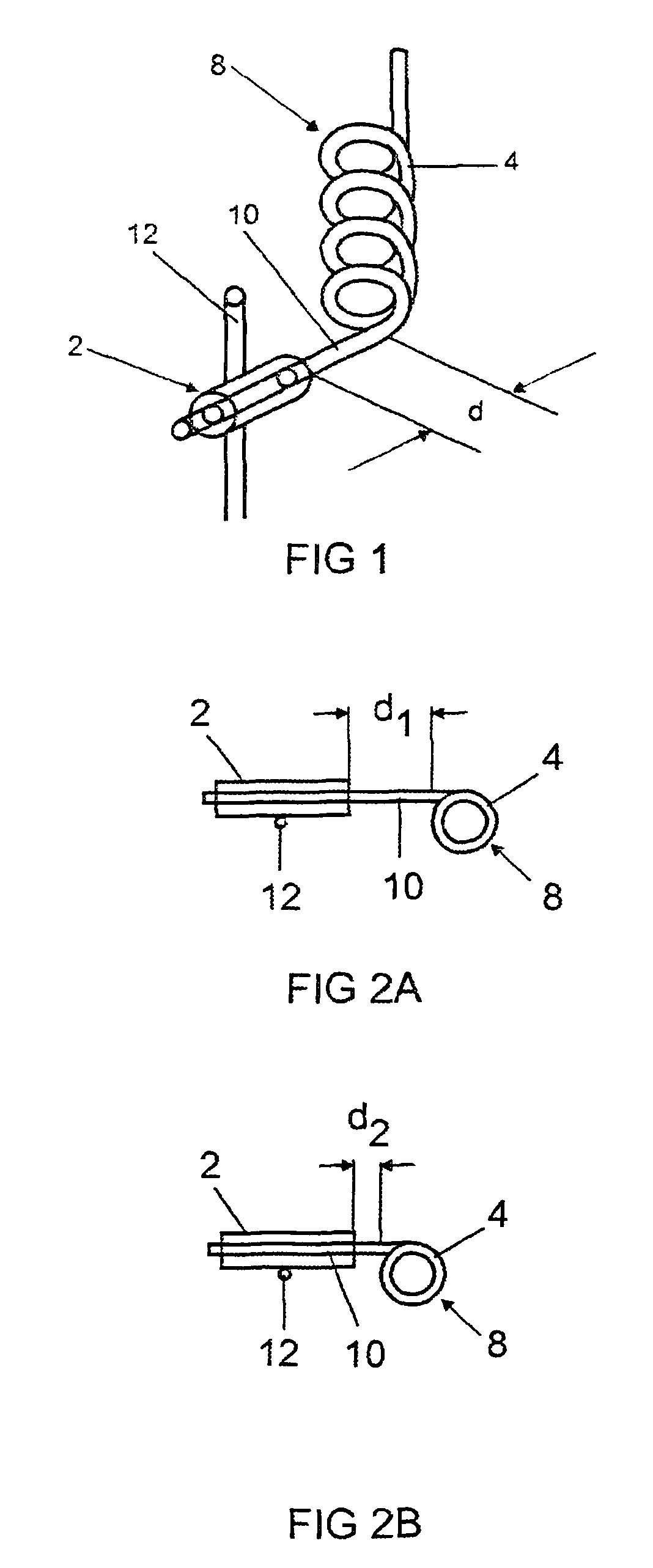
[0007]This object is achieved by a welding aid, as well as a lamp with such a welding aid and a method for attaching such a welding aid, wherein the welding aid is designed to connect an incandescent filament end to a current-conducting mount, and said welding aid is arranged at a certain distance d from the incandescent filament body, the distance d being fixed depending on a power P at which the lamp is operated.

[0008]Owing to this power-dependent scaling of the distance d between the welding aid and the incandescent filament body, it is firstly possible to minimize the distance d in the case of lamps with low wattages, as a result of which the component size can overall be reduced. Secondly, the optimized distance d makes it possible to reduce the temperatur...


PUM


Abstract

Disclosed are a welding aid for a spiral-wound filament of a lamp and a lamp comprising such a welding aid. The spiral-wound filament has a spiral-wound filament body and at least one spiral-wound filament tail. The welding aid is arranged at a distance d from the spiral-wound filament body and is designed to connect the at least one spiral-wound filament tail to a current-conducting support, the distance d being defined in accordance with a power P at which the lamp is operated.

Description

[0001]This application is a U.S. National Phase Application under 35 USC 371 of International Application PCT / EP2007 / 063360, filed Dec. 5, 2007, which is incorporated herein in its entirety by this reference.TECHNICAL FIELD[0002]The present invention relates to a welding aid for an incandescent filament of a lamp, to a lamp with such a welding aid, and to a method for attaching such a welding aid, the welding aid being designed to connect the incandescent filament to a current-conducting mount.PRIOR ART[0003]In general, the connection between an incandescent filament and a power supply line is produced by means of welding. For this purpose, so-called welding aids are used which usually consist of molybdenum and ensure that there is a fixed connection between the incandescent filament and the power supply line.[0004]In this case, as is described in the document U.S. Pat. No. 5,808,399, for example, a molybdenum foil is positioned around the end of the incandescent filament which is i...

Claims


Application Information

Patent Timeline
Patent Type & Authority Patents(United States)
IPC IPC(8): H01K1/50H01K1/00H01K3/00
CPCH01K1/16H01K1/18H01K3/06
Inventor AUER, FRANKBEHR, GERHARDHELBIG, PETERSEICHTER, CHRISTIANWITTMANN, KLAUSZELT, SASCHA
Owner OSRAM GMBH
Why Eureka
Try Eureka